BODY AND TRUCKBED
Page C-13
4GRCKTCPF5GTXKEG/CPWCN
4GCFCNNQH5GEVKQP$CPFVJKUUGEVKQPDGHQTGCVVGORVKPICP[RTQEGFWTG2C[RCTVKEWNCTCVVGPVKQPVQCNN0QVGU%CWVKQPUCPF9CTPKPIU
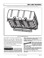
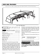
the cowl assembly (Ref Cowl Replacement Section on
page C-5). Carefully disconnect the battery negative (-)
cable first and then the positive (+) cable from the battery
using insulated wrench. Remove the battery (Refer Bat-
tery Removal and Installation in SAFETY). Remove the
direction and drive selector cables (Refer Direction and
Drive Selector Cable Adjustment in DIRECTION AND
DRIVE SELECTOR). Remove the master cylinder (Refer
to Master Cylinder Replacement in BRAKES). Remove
all the cables and wires connected to instrument panel
and note the wiring locations. Support upper mount
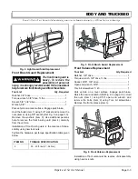
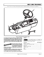
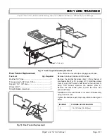
frame (item 1) of the instrument panel using lift (Ref Fig.
20 on page C-13).
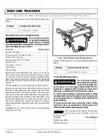
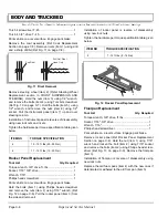
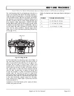
Hold the bolt (item 2) connecting upper mount frame to
the main frame using 9/16" wrench and remove the nut
(item 3) using 9/16" socket (Ref Fig. 21 on page C-14).
Remove the bolt (item 4) using 13mm wrench and
washer (item 5). Hold the bolt (item 6) using 1/2" wrench
and remove the nut (item 7) using 1/2" socket. Remove
the washer (item 8). Raise the whole instrument panel
(item 9). Hold the bolt (item 10) using 1/2" wrench and
remove the nut (item 11) using 1/2" socket. Remove the
washer (item 12). Hold the nut (item 13) using 9/16"
wrench and remove the bolt (item 14) using 9/16" socket.
Remove the screw (item 15) connecting front fender well
to the cowl and fender support using Torx bit screw-
driver. Remove the washer (item 16). Remove the front
fender well (item 17).
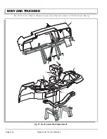
Installation of the front fender well is reverse of disas-
sembly using new lock nuts.
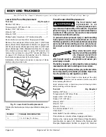
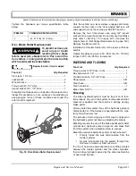
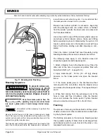
Tighten the hardware per torque specification table given
below.
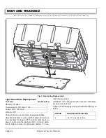
Fig. 20 Lifting Points
Lifting Points
1
ITEM NO
TORQUE SPECIFICATION
3
20 - 25 ft. lbs (27 - 34 Nm)
9
11 - 14 ft. lbs (15 - 19 Nm)
13
8 - 13 ft. lbs (11 - 21 Nm)
Содержание ST 4X4
Страница 6: ...Page iv Repair and Service Manual TABLE OF CONTENTS Notes...
Страница 10: ...Repair and Service Manual SAFETY INFORMATION Page viii Notes...
Страница 12: ...GENERAL INFORMATION ROUTINE MAINTENANCE Page A ii Repair and Service Manual Notes...
Страница 24: ...SAFETY Page B ii Repair and Service Manual Notes...
Страница 34: ...BODY AND TRUCKBED Page C ii Repair and Service Manual Notes...
Страница 50: ...BRAKES Page D ii Repair and Service Manual Notes...
Страница 68: ...CONTINUOUSLY VARIABLE TRANSMISSION CVT Page E ii Repair and Service Manual Notes...
Страница 74: ...DIRECTION AND DRIVE SELECTOR Page F ii Repair and Service Manual Notes...
Страница 80: ...ELECTRICAL Page G ii Repair and Service Manual Notes...
Страница 114: ...FRONT SUSPENSION AND STEERING Page J ii Repair and Service Manual Notes...
Страница 128: ...FUEL SYSTEM Page K ii Repair and Service Manual Notes...
Страница 136: ...PAINT Page L ii Repair and Service Manual Notes...
Страница 142: ...REAR AXLE AND SUSPENSION Page M ii Repair and Service Manual Notes...
Страница 152: ...SPEED CONTROL Page N ii Repair and Service Manual Notes...
Страница 160: ...TROUBLESHOOTING Page P ii Repair and Service Manual Notes...
Страница 168: ...WHEELS AND TIRES Page R ii Repair and Service Manual Notes...
Страница 174: ...GENERAL SPECIFICATIONS Page S ii Repair and Service Manual Notes...
Страница 180: ...LIMITED WARRANTY Page T ii Repair and Service Manual Notes...
Страница 182: ...Page T 2 Repair and Service Manual LIMITED WARRANTY Notes...

