background image


     SIMS PRO


82 


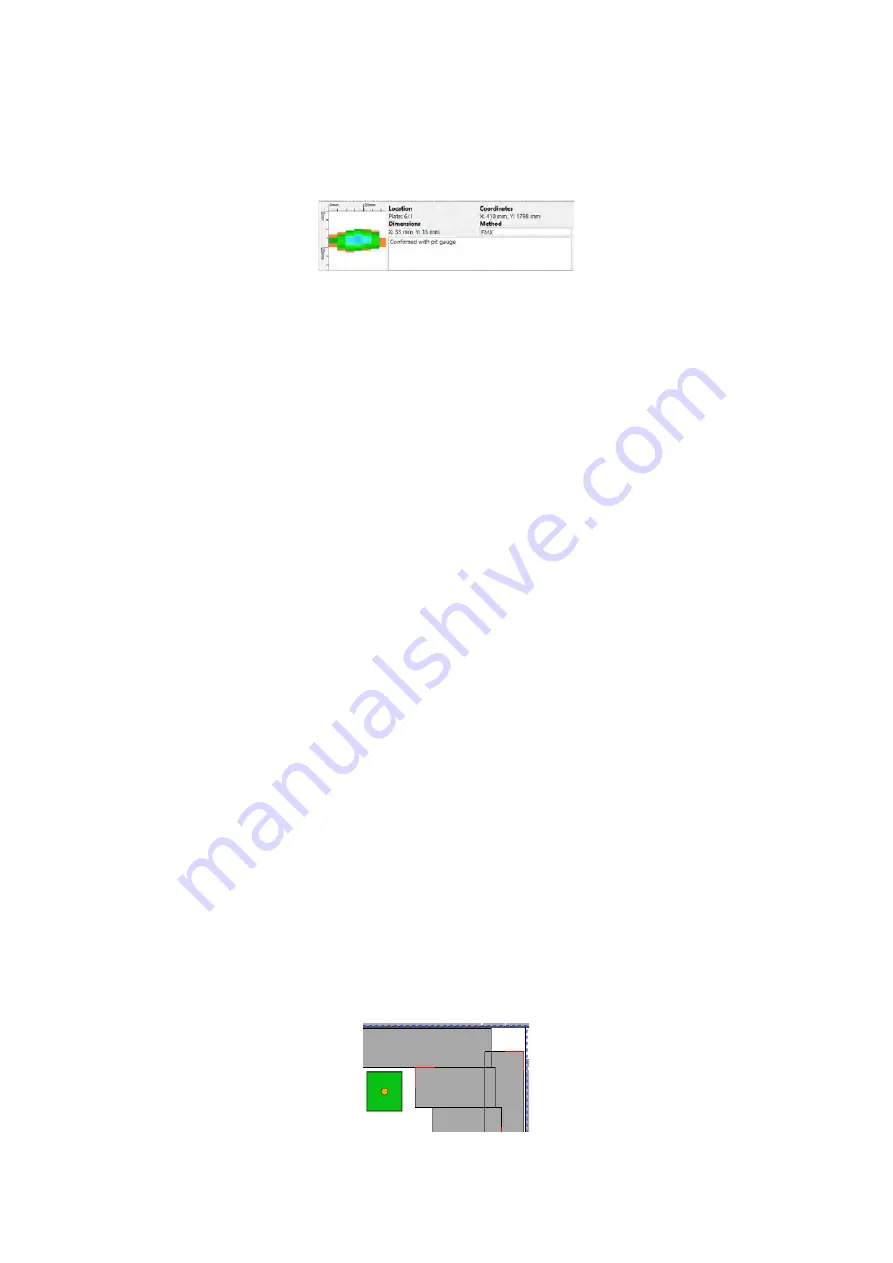
with a method of detection and any indication notes added during the inspection. Indication notes 
can be edited or added to any indication in the list, but method of detection can only be edited once 
the indication status has been set to accepted. Indication note can also be identified and viewed in 
the indication list by hovering the cursor on the speech bubble icon. 


Figure 107: Additional information for a selected indication 

Rejecting Indications  

To reject an indication: 

1.


Select a plate. 

2.


Click 

Indication List

 on the home ribbon. 

3.


Select an indication and change the status to 

Reject

, red square. 

Accepting Indications 

To accept an indication: 

1.


Select a plate. 

2.


Click 

Indication List 

on the home ribbon. 

3.


Select an indication and change the status to 

Accept,

 green circle. 

4.


Modify the indication by:  


Entering a prove up or estimated remaining value. 


Changing its surface origin.  


Alter the method. 

Cancel an indication modification 

To cancel a modification and revert the indication to the original status: 

1.


Select a plate. 

2.


Click 

Indication List

 on the home ribbon. 

3.


Select a modified indication in the list and return its status to 

MFLA

, orange triangle. 

Added Indications 

There are two indications shape options available for adding to the inspection layout. 

Rectangular 

To add a rectangular indication:  

1.


Click 

Rectangular

 on the home ribbon. 

2.


Click, hold, and drag to draw the rectangle indication. 

3.


Set the required properties for the rectangular indication. 


Figure 108: Rectangular indication 

Содержание Floormap X

Страница 1: ...User s Manual Floormap X MFL Array Tank Floor Inspection Solution...

Страница 2: ...e FloormapX system SIMS GO Software version 1 1R2 SIMS PRO Software version 1 2R3 The text figures and programs have been worked out with the utmost care However we cannot accept either legal responsi...

Страница 3: ...What s in the Box 20 2 2 FloormapX Overview 20 2 3 Assembling the FloormapX 31 2 4 Recommended Scanning Bridge Height 32 2 5 MFL Technique 33 2 6 Specifications 34 3 Inspection Process 36 3 1 Pre Insp...

Страница 4: ...ion 70 5 2 Installing SIMS PRO 70 5 3 Loading SIMS PRO 70 5 4 SIMS PRO Backstage 71 5 5 SIMS PRO Frontstage 77 5 6 Home Ribbon 80 5 7 Design Ribbon 85 5 8 Repair Ribbon 88 5 9 Report Ribbon 90 5 10 Re...

Страница 5: ...5 6 6 Scanning Head 103 6 7 Service 104 7 Troubleshooting 105 7 1 System won t power on 105 7 2 Motorization not functioning 105 7 3 Firmware version error message 105...

Страница 6: ...mapX battery compartment 28 Figure 19 FloormapX battery charger information 29 Figure 20 Offering the mainframe to the scanning head 31 Figure 21 Engaging the mainframe with the scanning head 31 Figur...

Страница 7: ...ure 56 Step 1 bottom surface scan 54 Figure 57 Step 2 bottom surface scan 54 Figure 58 Step 3 bottom surface scan 54 Figure 59 Load calibration 55 Figure 60 Importing calibration from another inspecti...

Страница 8: ...ard 70 Figure 92 SIMS PRO desktop icon 70 Figure 93 SIMS PRO backstage home 71 Figure 94 Import data wizard asset selection 72 Figure 95 Import data wizard import data 72 Figure 96 Load inspection wiz...

Страница 9: ...re 121 Patch plate list tool window 89 Figure 122 Report ribbon 90 Figure 123 Report document window 90 Figure 124 Report wizard options 91 Figure 125 Plate property reportable options 91 Figure 126 R...

Страница 10: ...10 Chapter 1 Precautions and conventions...

Страница 11: ...e substitute parts or perform unauthorized modifications to the system Service instructions when applicable are intended for trained service personnel only Ensure by regular checks that the working si...

Страница 12: ...tices Care should be taken during tank ingress and egress through the access manway The system must be lifted by two suitably strong persons Magnetic Attraction Due to the strong magnetism involved lo...

Страница 13: ...t is safe to operate The equipment when used as intended according to its user manual complies with the essential requirements of the following Low Voltage Directive LVD 2014 35 EU the Radio Equipment...

Страница 14: ...kers and defibrillators People with pacemakers or ICD s must stay at least 2 m 6 5 ft away WARNING FINGER TRAP Tools magnets and metal objects can cut pinch or entrap hands and fingers HANDLE WITH CAR...

Страница 15: ...art 15 subpart B and ICES 003 FCC Compliance USA This equipment was tested and found to comply with the limits for a Class A digital device pursuant to Part 15 of the FCC Rules These limits are design...

Страница 16: ...General Precautions and Conventions 16 1 5 EU Declaration of Conformity...

Страница 17: ...r ninety 90 days from the completion of repair Upon Customer s written notice of defect within the ninety 90 day period EDDYFI will replace the defective part s and or re perform the service This warr...

Страница 18: ...revenue or other commercial or economics losses loss of use of the product or any associated equipment downtime the claims of third parties including Customer damage to property or injury to personne...

Страница 19: ...19 Chapter 2 FloormapX System Overview...

Страница 20: ...h modes can adopt a pause on defect workflow 2 1 What s in the Box The FloormapX is supplied in two rugged transport cases and comes with the following standard accessories Mainframe box FloormapX mai...

Страница 21: ...of 0 to 100 When the indicator points to the zero 0 position then the FloormapX magnets are deemed off and do not impart magnetism into the inspection surface When the magnetic indicator points at any...

Страница 22: ...r the probe cables NOTE To avoid damage when assembling the FloormapX please ensure cables are attached after the modules have been correctly assembled and verified as secure Cover Plate The cover pla...

Страница 23: ...e connector for the tablet to mainframe cable This cable runs through the docking station and into the mainframe IMPORTANT Care must be taken during assembly disassembly and altering the viewing angle...

Страница 24: ...se ensure the Emergency Stop has not been accidentally pressed especially when assembling the FloormapX from the component modules Laser and rear light module Located at the rear of the mainframe is t...

Страница 25: ...cable is disconnected IMPORTANT After installation or adjustment of the user control height ensure the locking plunger is properly engaged before using the system Failure to do so will invalidate the...

Страница 26: ...steering angle Press down the steering knob to return to a straight line Tablet The FloormapX tablet is a quick release detachable module that is secured in the docking station of the mainframe and c...

Страница 27: ...view Select active view Selects the active view within the calibration and scan page The active view is indicated by the purple boarder Full extent Returns the zoom level to see the entirety of the p...

Страница 28: ...me label In the front of the mainframe behind the removable cover is the battery compartment where two battery slots are located When viewing the system from the front the right hand active battery sl...

Страница 29: ...urn off 2 Remove the battery front cover by unscrewing the two thumbscrews 3 Release the battery locking cam by turning counter clockwise 4 Using the carry handle remove battery from the FloormapX Cha...

Страница 30: ...of charging and discharging for full battery capacity to be recovered The FloormapX battery charger is only designed for indoor use and should not encounter water or dust To avoid overheating the char...

Страница 31: ...nframe to the scanner head rear attach mechanism Figure 20 Offering the mainframe to the scanning head 8 With a foot placed in front of the scanner head to stop it rolling engage the mainframe rear at...

Страница 32: ...ff the battery must be removed from the right hand active battery slot and placed into the left hand storage slot The battery capacity has a potential of discharging if left in the active slot when th...

Страница 33: ...greater than 12mm 1 2in 2 5 MFL Technique To detect a leaking field the FloormapX uses hall effect sensors mounted between the poles of a magnetic bridge The magnetic bridges include strong permanent...

Страница 34: ...Box 1 45kg 99lbs Box 2 55kg 121lbs Shipped dimensions Box 1 510mm x 650mm x 370mm Box 2 1220mm x 490mm x 420mm 20 x 25 6 x 14 6 in 48 x 19 3 x 16 5 in Assembled weight 63 kg 139 lbs Minimum man way si...

Страница 35: ...35 Chapter 3 Inspection Preparation Setup and Operation...

Страница 36: ...powering on the system 3 Check all cables are free and not pinched 4 Ensure the cover plate is attached and fixed in place 5 Ensure the scanning bridge high low mechanism is free moving and locks in...

Страница 37: ...owing the inspection surface thickness and selecting the correct reference plate for calibration is vital to obtaining optimal results when using the FloormapX system When the inspection surface is Th...

Страница 38: ...ommended to set the magnet position to zero before cleaning as most magnetic debris will fall away from the scanner without further action since there is no magnetic attracting force 4 Locate the tank...

Страница 39: ...plate numbering system for report generation in the SIMS PRO software Figure 28 Plate numbering system with bottom left tank datum position 10 For annular numbers set the position of the annular plat...

Страница 40: ...s for scan width IMPORTANT Marking out the plate tracks before or during inspection can increase inspection efficiency when scanning tank floors NOTE It is advised to mark out track width intervals at...

Страница 41: ...spection surface however due to a positional offset between these two sensors head at the start of a scan data captured begins at the MFL sensor head location while at the end of a scan data captured...

Страница 42: ...nsit case for shipping REMOVE BATTERY When the FloormapX system is powered off the battery must be removed from the right hand active battery slot and placed into the left hand storage slot The batter...

Страница 43: ...43 Chapter 4 SIMS GO Data Acquisition Software...

Страница 44: ...he home button in the upper left corner Alternatively return to the desired frontstage window by selecting from the ribbon tab 4 2 Backstage An icon toolbar across the top of the backstage window allo...

Страница 45: ...or example if the annular plate thickness does not match the reference plate thickness it prevents you from inspecting that plate thus ensuring the correct calibration is used The correct tank diamete...

Страница 46: ...me name will be replaced Click Yes to replace the inspection or click No to cancel Multiple inspections can be selected and either exported or imported at the same time and the warning messages option...

Страница 47: ...to the backstage click Cancel NOTE Used calibrations cannot be deleted Plate List The plate list option opens the plate list menu and lists every plate created within that inspection Figure 37 Plate l...

Страница 48: ...em This section contains main preferences to handle parameters specific to the system Figure 39 Backstage system The software can be set to either metric or imperial in the measurement units This modi...

Страница 49: ...o 51 3 Green bars Medium 52 to 67 4 Green bars High 68 to 84 5 Green bars Full 84 and higher Charging icon Charging Charging Display Preferences This section contains the management of the tablet s di...

Страница 50: ...he current license information fields NOTE A valid internet connection is required to connect to the licensing server Click Edit allows modification to the contact information for the contact person t...

Страница 51: ...nd anonymous 4 3 Frontstage Layout The frontstage is accessed by selecting one of the tabs above the ribbon at the top of the window Figure 45 Frontstage ribbon The first tab is the inspection tab and...

Страница 52: ...g the column title To view a plate in the plate view page select a plate in the list and click Open The cancel button closes the plate list and returns to inspection Indication List The indication lis...

Страница 53: ...ations location and dimension values cannot be edited 2 Manual indication These can be placed anywhere in the plate view by using the add indication tool When adding a manual indication its status is...

Страница 54: ...anner has been correctly set Refer to the recommended scanning bridge height section 2 Prepare the reference plate for a top surface scan then follow the scan sequence Figure 52 Step 1 top surface sca...

Страница 55: ...bridge strength The used checkbox on the right hand side indicates if that calibration has been used to scan a plate in the current inspection The buttons allow for deleting a selected calibration lo...

Страница 56: ...ays a purple exclamation mark Once the expected calibration is loaded the cal loaded info field background turns to white and a green checkmark displays at the left of the calibration ribbon Figure 62...

Страница 57: ...Plate Dimensions The maximum dimensions for the plate length and width are entered into the relevant boxes The plate length dimension range is from 450mm to 15500mm 17 7in to 610in and the plate width...

Страница 58: ...scan is located The number and position of the possible plate reference locations available relate to the geometry of that plate For rectangular and sketch plates all 4 origins are available For annul...

Страница 59: ...ce of the scanning head to the shell wall If the scanner is against the shell wall the shell offset is zero Figure 71 Shell offset measurement Figure 72 Scanning head side black casing notch Creating...

Страница 60: ...hin that inspection Figure 76 Plate list The list also shows related information for each plate Max indication the EPL value of the maximum depth indication Threshold indications the number of indicat...

Страница 61: ...and end x y reference co ordinates for the added scan are determined by measuring from the reference corner of the plate to the chosen reference point of the scanner either the left hand or right hand...

Страница 62: ...deviate from a pre planned scanning pattern by selecting a different track to scan changing the scan direction or by altering the start scan offset value Figure 79 Scan options Track Track selection a...

Страница 63: ...elected the offset value is calculated by measuring the distance between the laser line Figure 81 Start scan position resume IMPORTANT Mark the laser line on the floor before repositioning the scanner...

Страница 64: ...ta views for a plate can be switched between the available options Top Bottom show top and bottom indications from the scans Top show only the top indications from the scans Bottom show only the botto...

Страница 65: ...ue or Est Remain value Rejected indications are hidden from the scan view but still shown in the list Figure 84 Tablet button to change indication status The indication list button opens the indicatio...

Страница 66: ...ntirety of the scan Display Threshold The display threshold button allows the minimum estimated percentage level value from which indications should be displayed from in plate view and scan view to be...

Страница 67: ...number track number or starting offset information is required prior to scanning All positional information of a Freescan is referenced to its scan origin Figure 88 Freescan page The Freescan option i...

Страница 68: ...are suggested SIMS GO screening or mapping workflows Screening Inspection Workflow Below is a typical workflow of the software menus required to perform a screening inspection using the Freescan Figur...

Страница 69: ...69 Chapter 5 SIMS PRO...

Страница 70: ...re 91 SIMS PRO installation wizard During the installation you will be given an opportunity to join the Eddyfi Technologies Product Improvement Program This is a voluntary program which you can opt ou...

Страница 71: ...file into the loaded inspection Export This option is available once an inspection is loaded in the frontstage Here you can export data for the loaded inspection into an excel file The data available...

Страница 72: ...the list and click Next Or if a new asset is required click Add Asset and enter the required information then click Create Figure 94 Import data wizard asset selection 3 From the dropdown select the i...

Страница 73: ...SIMS PRO displays the inspection data in the frontstage of the software Deleting Inspection Data Inspection data can be deleted from the SIMS PRO database To remove 1 In the backstage home menu click...

Страница 74: ...al indication template 1 In the backstage on the sidebar click Templates 2 Select Excel Manual Indication Template option 3 Choose the desired measurement system for the template file 4 Click Browse t...

Страница 75: ...pection Once imported the manual indications or patch plates are automatically added to the inspection layout and included in the lists To import a template file 1 In the backstage on the sidebar clic...

Страница 76: ...rt location and file name for the exported indication list 4 Configure the export list by ticking the required options then click Export The list is saved to the exported location and opens using the...

Страница 77: ...h as applying patch plates to the layout Report Allows for the generation of reports using the report wizard or custom report Data Allows for the import additional data or replace existing data to the...

Страница 78: ...data STARS F5 displays raw data captured with the STARS Setting Layout Units The inspection data displayed in the layout view can be either in metric or imperial values To set the units 1 Click File...

Страница 79: ...upon the item selected there are simple operations that can be performed Layout Properties To view the basic layout properties select the white background of the layout Properties include Asset ID Ta...

Страница 80: ...the maximum indication found on it Surface ID Indications are colored in terms of their surface origin Blue color is Bottom surface indications Red color is Top surface indications Green color is Both...

Страница 81: ...f an indication can be modified as well as entering a prove up value altering the detection method and adding a comment to indications The list only displays indications that have been selected in the...

Страница 82: ...cation 1 Select a plate 2 Click Indication List on the home ribbon 3 Select an indication and change the status to Accept green circle 4 Modify the indication by Entering a prove up or estimated remai...

Страница 83: ...the required properties for the note marker Figure 110 Note marker Attachments To add a photograph a pdf or other attachment file 1 Click Note Marker on the home ribbon 2 Click on the layout to positi...

Страница 84: ...n viewer tool window Notification Center The notification center window provides you with additional information on certain actions and can be useful when an unforeseen event occurs This window pops u...

Страница 85: ...ibbon allows tank design operations such as setup and editing of plates their layout position the numbering and adding customization features Figure 114 Design ribbon Tank North To set the tank north...

Страница 86: ...t To create an annular ring 1 Click Annular Ring on the design ribbon 2 Enter all annular ring information into the create annular ring window 3 Click OK Figure 116 Create annular ring wizard Edit Pla...

Страница 87: ...eatures The available tank components include Manway Nozzle Sump Circular Sump Rectangular Support Circular Support Rectangular Tank Components To add a tank component 1 Click the Tank Component butto...

Страница 88: ...Close the freeform by double clicking or return the cursor to the red square at the start position 5 Set the required properties for the freeform Add Text To draw a text box 1 Click Draw Text on the d...

Страница 89: ...rence position that the patch is located on to the patch reference position The measurement reference for a patch can be set to be either the patch center or the top left corner and is set in the repa...

Страница 90: ...the report wizard or when a blank report is selected The report document window consists of the following sections Report tools ribbon when the report document is selected Tool bar at the top of the...

Страница 91: ...le elements in the properties 3 Click hold and drag the reportable element onto the report document 4 Select the reportable element in the report document 5 In the properties set the customization opt...

Страница 92: ...n the report tools ribbon select one of the options Metric Imperial Page Setup To set the page size 1 Select the report document 2 In report units on the report tools ribbon select one of the options...

Страница 93: ...n allows the importation of additional inspection data and replacing plate data Import Additional Plates To importing additional plates into an existing inspection 1 Load the inspection that required...

Страница 94: ...es the indication selection outline for each indication within the region NOTE Further individual indications can be added or removed from the selection by holding the Ctrl key and selecting indicatio...

Страница 95: ...nt plate threshold range the indications are no longer shown on the plate but the indication selection box outlines remain visible since they are still selected 2 Alter the selected indications by inc...

Страница 96: ...the selected indications to become both and set the status to accepted IMPORTANT The EPL value for selected bottom indications become adjusted based upon the top surface calibration trace Reset Indic...

Страница 97: ...dification ribbon can be changed between either a Parallel or a Raster scanning format Plate Size The dimensions entered for the plate during data acquisition software can be changed in the plate prop...

Страница 98: ...98 Chapter 6 Troubleshooting and Maintenance...

Страница 99: ...ence A full report describing the damage in detail must be submitted to the transport company and serves as the basis for the damage claim Damage or loss of goods delivered must be reported immediatel...

Страница 100: ...he active slot when the system is not powered on 4 Remove the motorization and sensor cables between the mainframe and scanner head Place these into the mainframe case 5 Whilst supporting the mainfram...

Страница 101: ...e down on the user control 5 Disconnect the mainframe to docking connector for the tablet 6 Loosen the tablet docking angle adjustor knob and fold the docking with tablet flat against the front of the...

Страница 102: ...ablet functions contact Eddyfi for fault finding information and troubleshooting 6 4 User control Cleaning The user control can be cleaned with a damp cloth It is important that the height adjust plun...

Страница 103: ...should be wiped away from the system A vacuum cleaner is also an excellent option for removing ferrous material The system may be cleaned in general with a damp cloth The wheels should be cleaned wit...

Страница 104: ...Manual override of steering It is possible to manually override the steering system should the steering motor fail Please contact an Eddyfi service center for advice and instruction on this matter be...

Страница 105: ...red knob All cables are correctly connected check with system power off NOTE The magnets will not turn on unless in the scan environment i e in Freescan or mapping modes If the motors will still not o...

Страница 106: ...gies Eddyfi Silverwing Floormap SIMS and their associated logos are trademarks or registered trademarks of Eddyfi Canada Inc in the United States and or other countries Eddyfi Technologies reserves th...

Отзывы: