Chapter 4 Parameters
4-153
this way a system can be stable without steady-state fault by proportional gain control and integral
time control.
3. Differential control (D): the controller output is proportional to the differential of the controller input.
During elimination of the fault, oscillation or instability may occur. The differential control can be used
to suppress these effects by acting before the fault. That is, when the fault is near 0, the differential
control should be 0. Proportional gain (P) + differential control (D) can be used to improve the system
state during PID adjustment.
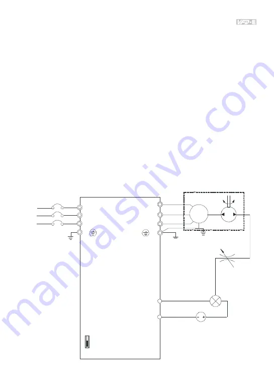
D. When PID control is used in a constant pressure pump feedback application:
Set the application’s constant pressure value (bar) to be the setpoint of PID control. The pressure
sensor will send the actual value as PID feedback value. After comparing the PID setpoint and PID
feedback, there will be a fault. Thus, the PID controller needs to calculate the output by using
proportional gain(P), integral time(I) and differential time(D) to control the pump. It controls the drive
to have different pump speed and achieves constant pressure control by using a 4-20mA signal
corresponding to 0-10 bar as feedback to the drive.
ACI/AVI
(4~20mA/0-10V)
ACM
U(T1)
V(T2)
W(T3)
IM
E
AV 2
I
ACI
VFD-E
R(L1)
S(L2)
T(L3)
(NFB)
R
S
T
E
DC
no fuse breaker
water pump
switch
analog signal common
feedback 4-20mA
corresponds to
0-10 bar
pressure
sensor
throttle
Содержание VFD-E Series
Страница 271: ...B 6 B 1 4 DIN Rail Installation...
Страница 304: ...B 39 Driver Installation After connecting IFD6500 to PC please install driver by following steps...
Страница 305: ...B 40 LED Display 1 Steady Green LED ON power is ON 2 Blinking orange LED data is transmitting...
Страница 306: ...B 41 B 9 DIN Rail B 9 1 MKE DRA Unit mm inch SCREW M4 2X 20 22 Kgf cm...
Страница 335: ...D 8 In ladder diagram mode you can perform program editing using the buttons on the function icon row Basic Operation...


