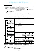
2-26
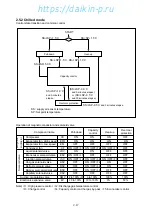
I : Capacity control
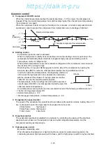
In the chilled mode operation, adjusting cooling capacity makes the supply air temperature stable at
the set point temperature (SP).
The capacity control is executed by adjusting the opening of suction modulating valve (SMV)
between 3 to 100 %.
J : Charge and release control
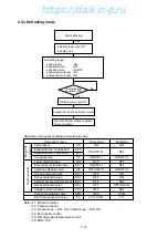
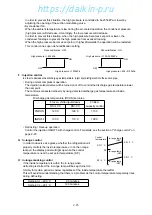
Charge control or release control is executed to maintain the heating capacity optimum in defrosting
and heating operation.
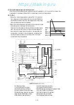
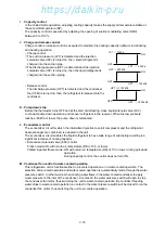
• Charge control
q
The suction pressure (LPT) is detected and the injection
solenoid valve (ISV) is turned on, then, liquid refrigerant is
charged into the suction pipe.
w
The discharge pressure (HPT) is detected and the injection
solenoid valve (ISV) is turned on, then the liquid refrigerant is
charged into the suction piping.
• Release control
The discharge pressure (HPT) is detected and the condenser
fan (CFM) is turned on, then, the refrigerant is released into the
condenser.
K : Pump down stop
Before the thermostat turns OFF and at the start of defrosting, close liquid solenoid valve (LSV)
to conduct pump down operation and recover refrigerant in the receiver. When the low pressure
reaches –50kPa or lower, the pump down is terminated.
L : Economizer control
The economizer circuit for which the intermittent injection to scroll compressor and the refrigerant
heat exchanger are combined, is adopted in the unit.
The economizer circuit enables the liquid refrigerant to have wide range of subcooling resulting in a
significant increase of cooling capacity.
• Economizer solenoid valve (ESV) control
Frozen mode: ON with return air temperature (RS) of 5˚C or lower
Chilled & partial frozen mode: ON with return air temperature (RS) of 5˚C or lower during pull-down
operation
During capacity control, the control does not turn ON.
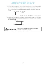
M : Condenser fan control in water-cooled operation
This refrigeration unit is functional either in air-cooled operation or in water-cooled operation. The
selection of air-cooled operation and water-cooled operation is automatically made through the water
pressure switch. In other words, when cooling water flows in the water cooled condenser to apply
water pressure to the inlet of the condenser, a contact in the water pressure switch will open to stop
the condenser fan motor, thus switching the unit to water-cooled operation. By contrast, if feeding
water stops in water-cooled operation, a contact in the water pressure switch will be closed to run the
condenser fan motor, thus switching the unit to air-cooled operation.
HPT
>
1200 kPa
HPT
≦
1150 kPa
ON
OFF
LPT
<
40 kPa
LPT
>
70 kPa
ON
OFF
HPT
<
700 kPa
HPT
>
800 kPa
ON
OFF
https://daikin-p.ru
Содержание LXE10E-1
Страница 161: ...7 9 https daikin p ru ...
Страница 162: ...7 14 Schematic wiring diagram LXE10E 1 7 10 https daikin p ru ...
Страница 163: ...7 15 Stereoscopic wiring diagram LXE10E 1 7 11 https daikin p ru ...

