4-20
2. Replacement of body
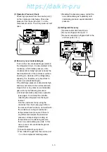
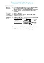
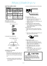
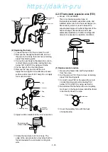
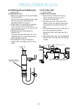
(1) Remove the coil. Refer to the section 1.
"Replacing the coil" for removing procedure.
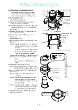
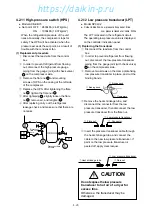
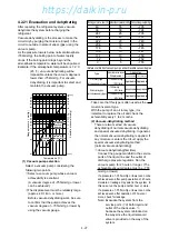
(2) Remove the heat insulator
q
for the SMV after
cut the binding band
w
.
(3) Heat up the brazed joint on the piping of SMV
body to disconnect the pipe at brazed section.
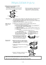
(4) Assemble piping of the SMV body, and conduct
brazing while keeping the temperature of lower
body of SMV below 120˚C (248˚F) by covering
the body with wet cloth.
Note) When brazing, to keep the temperature of
body, including value body, coil, lead
wire, etc. below 120˚C by supplying
water.
In this work, be sure to prevent water
from entering into the lead wire protection
tube.
(5) Install the heat insulator
q
and fasten it with
bandling band
w
.
(6) Install the coil. Refer to the section 1.
"Replacing the coil" for removing procedure.
w
Bandling band
q
Heat insulator
q
Heat insulator
Suction modulating
valve body
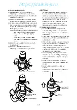
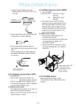
4.2.7 Drier
The drier automatically absorbs moisture in
the refrigerant while it is circulated. It also
commonly works as a filter to remove dust in
the refrigerant. Replace the drier if it does not
absorb moisture or if it is blocked. When
installing the new drier, follow the directions
given on the label and do not make any
mistake about the flow direction of the drier.
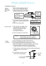
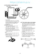
(1) Replacement procedure
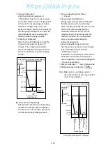
q
Conduct the automatic pump down to
collect the refrigerant in the liquid receiver.
Refer to page 4-3 and 4-4 for the automatic
pump down.
w
Then, quickly replace the drier with a new one
after loosening the flare nuts on the inlet and
outlet side of the drier.
e
When the flare nuts are loosened, if no sound
of gas refrigerant leakage is detected at the
flare nut section, then air mixing into the
refrigerant is suspected. In this case, conduct
vacuum-dehydrating from the quick joint
located at the inlet side of drier.
r
After completing of the replacement of the
drier, be sure to conduct refrigerant leakage
test to confirm that no refrigerant leakage is
occuring.
t
Check on the green colour of the liquid /
moisture indictor after system operation has
started.
y
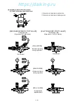
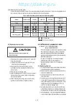
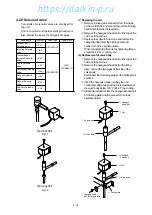
Apply a sillicon sealant to the flare nut
section.
Adhere some anti-corrosion tape to the flare
nut section.
Flare nut
Flare nut
Quick joint
Seal using with
sillicon Sealant
https://daikin-p.ru
Содержание LXE10E-1
Страница 161: ...7 9 https daikin p ru ...
Страница 162: ...7 14 Schematic wiring diagram LXE10E 1 7 10 https daikin p ru ...
Страница 163: ...7 15 Stereoscopic wiring diagram LXE10E 1 7 11 https daikin p ru ...

