4-23
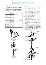
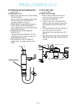
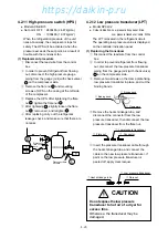
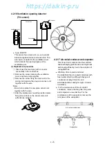
4.2.11 High-pressure switch (HPS)
●
Model ACB-KB15
●
Set point OFF : 2400kPa (24.47kg/cm
2
)
ON
: 1900kPa (19.37kg/cm
2
)
When the refrigeration pressure of the unit
rises abnormally, the compressor stops for
safety. The HPS will be activated when the
pressure exceeds the set point, as a result of
trouble with the condenser fan.
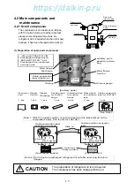
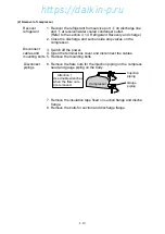
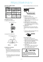
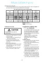
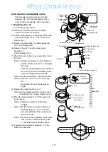
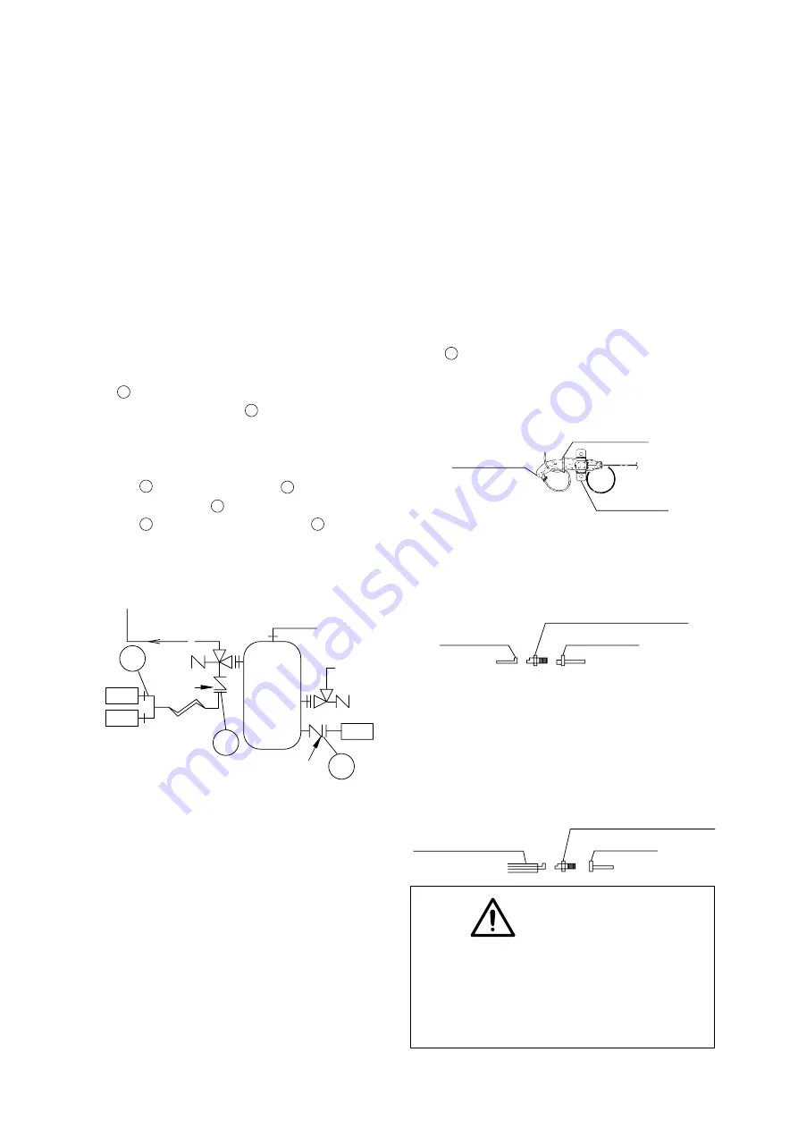
(1) Replacement procedure
q
Disconnect the lead wire from the control
box.
w
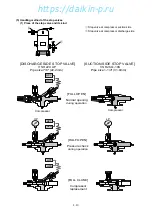
In order to prevent refrigerant from flowing
out, disconnect the high-pressure gauge
piping from the gauge joint (with check valve)
A on the compressor side.
e
Remove the flare nut B and mounting
screws of HPS on the casing at the left side
of the compressor.
r
Replace the HPS. After tightening the flare
nut B , tighten the flare nut A .
t
After tightening A , slightly loosen the flare
nut B , remove air, and retighten B .
y
After replacing carry out the refrigerant
leakage check, and make sure that there are
no leaks.
Disconnect
flare nut
here
Disconnect flare
nut here
B
A
C
COMPRESSOR
L P T
H P T
H P S
D
CAUTION
Do not expose the low pressure
transducer to hot air of a dryer for
excess time.
Otherwise, the transducer may be
damaged.
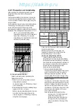
4.2.12 Low pressure transducer (LPT)
●
Model SPCL02
●
Colour indication: Low pressure transducer: Blue
Low pressure transducer: cable: White
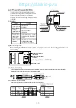
The LPT is located in the refrigerant circuit.
The operating low pressure value is displayed
on the controller indication panel.
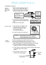
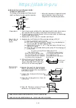
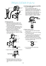
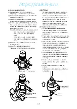
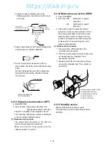
(1) Replacing the transducer
q
Disconnect the lead wire from the control
box.
w
In order to prevent refrigerant from flowing
out, disconnect the low-pressure transducer
piping from the gauge joint (with check valve)
C on the compressor side.
e
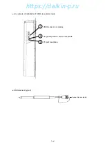
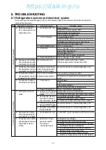
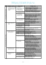
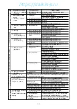
Remove two screws on the clamp plate fixing
low pressure transducer in place, and cut the
binding bands.
t
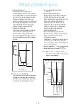
Insert the pressure transducer cable through
the heat shrinkage tube, and connect the
cable to the new low pressure transducer. If
paint on the low pressure transducer is
peeled off, apply clear lacquer.
r
Remove the heat shrinkage tube, and
disconnect the connector from the low
pressure transducer, then disconnect the low
pressure transducer from the flare nut.
q
Clamp plate
w
Binding band
w
Binding band
e
Connector
q
Low pressure transducer
w
Flare nut
e
Flare nut
q
Heat shrinkage tube
w
Low pressure transducer
https://daikin-p.ru
Содержание LXE10E-1
Страница 161: ...7 9 https daikin p ru ...
Страница 162: ...7 14 Schematic wiring diagram LXE10E 1 7 10 https daikin p ru ...
Страница 163: ...7 15 Stereoscopic wiring diagram LXE10E 1 7 11 https daikin p ru ...

