3-42
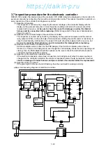
3.7 Inspection procedure for the electronic controller
DECOS
3
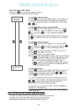
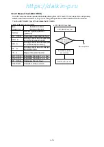
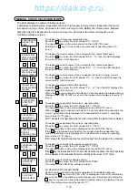
d enables the internal data of the controller CPU (RAM data) to be displayed on the monitor of a
personal computer by connecting the two with a communication cable. This makes it possible to preform an
easy inspection of the controller and diagnose any defect.
(1) Inspection of sensors
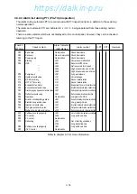
The inspection is carried out by comparing the sensor readings on the controller display with the
display on the personal computer. In case the sensor reading is abnormal, the sensor should be
replaced with a new one, but be sure to check the sensor for damage as well as the internal
harness and its connectors before replacing. (Refer to Appendix for the sensor characteristics.)
Page 7-4 and 7-5.
(2) Inspection of the internal relays of the electronic controller
The inspection is carried out by checking the display on the personal computer and the internal
relay output (24VAC) on the terminals of terminal board, utilizing the electric tester or test lamp. In
case the internal relay malfunctions, the power I/O board should be replaced with a new one, but
be sure to check the internal harness and its connectors for damage before replacing.
(3) Inspection of the Suction modulation valve
Suction modulation valve is driven by the PCB adapter. If the Suction modulation valve does not
function (i.e. if there is no clicking sound, ever though the control display shows the valve openning and
closing), then the PCB adapter should be replaced, but be sure to check the internal harness and its
connectors for damage before replacing.
(4) Inspection of the electronic expansion valve
If the electronic expansion valve does not operate (no clicking sound) when the valve opening is
changed on the controller indication, the electronic expansion valve should be replaced. However,
check on damage of internal harness and poor contact of connector before the replacement.
(5) Inspection of the cpu board
If the green light on the cpu board is flashing, then the cpu board is working normally.
●
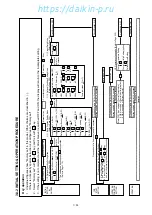
Basic internal wiring diagram of electronic controller
BAT
SMV
EV
CPU board
CN14
VOD
CN20
A/D
converter
CPU
CN17
CN18
CN16
CN13
PT/CT
board
Display
board
Sheet key
CN
20
CN
19
Power I/O board
Relay
driver
MV
driver
Relay
PHC
CN25
CN21
CN82
CN83
CN84
CN81
TrC
External output
and WPS/HPS/CTP
input
Adopter board
Sensor input
TB1
CN2
CN1
CN3
CN4
CN7
CN6
CN5
TES3
MV
https://daikin-p.ru
Содержание LXE10E-1
Страница 161: ...7 9 https daikin p ru ...
Страница 162: ...7 14 Schematic wiring diagram LXE10E 1 7 10 https daikin p ru ...
Страница 163: ...7 15 Stereoscopic wiring diagram LXE10E 1 7 11 https daikin p ru ...

