2-6
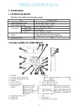
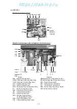
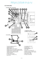
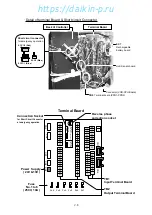
2.2.3 Control box
q
Controller operation panel (EC3, 4)
w
MANUAL DEFROST key
e
UNIT ON/OFF key
r
Phase correction contactor (PCC1,2)
t
Magnetic contactor for low speed evaporator fan (EFL)
y
Magnetic contactor for high speed evaporator fan (EFH)
u
Magnetic contactor condenser fan (CFC)
i
Reverse phase protection device (RPP)
o
Adopter PCB (EC6)
!0
Terminal block board (TB1)
!1
Controller CPU / IO board (EC1, 2)
!2
Fuse (Fu1-6)
!3
Rechargeable battery (BAT)
!4
Voltage indicator
!5
Personal computer receptacle
!6
Circuit breaker (CB)
!7
PT/CT board
!8
Transformer (TrC), control circuit
!9
Magnetic contactor for compressor (CC)
@0
P.C.B for humidity sensor (HUS, optional)
@1
Modem (RCD, optional)
@2
Noise filter (NF, optional)
@3
Control box sensor (CBS)
●
Operation panel
(Outside of the control box)
●
Controller
●
Inside of the control box
2
3
1
2 0
1 0
9
2 2
1 5
2 1
4
1 4
1 7
5
2 3
1 1
1 3
1 1
1 6
8
1 9
1 2
7
1 8
6
https://daikin-p.ru
Содержание LXE10E-1
Страница 161: ...7 9 https daikin p ru ...
Страница 162: ...7 14 Schematic wiring diagram LXE10E 1 7 10 https daikin p ru ...
Страница 163: ...7 15 Stereoscopic wiring diagram LXE10E 1 7 11 https daikin p ru ...

