


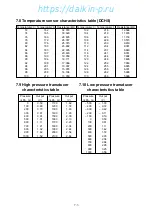


6-13
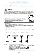
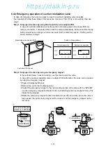
6.4.2 Short circuit operation of controller
Operate continuously for heating operation.
For cooling operation, go to next step
u
.
q
Turn the circuit breaker OFF.
w
Disconnect the power supply
connector CN82(White) on SMV
adapter board.
e
Remove Short Circuit Connector
SCC1-1(Blue), SCC1-2(Red) and
SCC2(Blue) stored on back of
controller.
r
Connect the Short Circuit Connector SCC1-2(Red) to CN8
and SCC2(Blue) to CN10 on terminal board.
t
Turn the circuit breaker ON.
If the power is in reverse phase,
EFM runs reversely with high speed.
Then fresh air is sucked to Outlet
Hole and discharged from Inlet
Hole at the lower ventilator.
y
If it is in reverse phase, turn the circuit breaker OFF and
replace the reverse phase correction socket to opposite side.
("Lower socket CN-C1 to Upper CN-C2"
or "Upper CN-C2 to Lower CN-C1")
For cutting off
the power to
CPU board
For making the
forced running
of CFM and
EFM.
For checking
reverse phase
power
For correction
of reverse
phase power
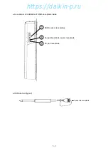
Disconnect CN82 (White)
Open cover
SMV adapter
SCC1-1(Blue)
SCC2(Blue)
SCC1-2(Red)
Lower ventilator
Air outlet
Air inlet
C O R R E C T
R E V E R S E
Air outlet
Air inlet
Reverse phase correction socket
(Refer to next step
y
)
Terminal Board
SCC1-2(Red)
CN-C2
CN-C1
SCC2(Blue)
u
Connect Short Circuit Connector SCC1-1(Blue) to CN8
and SCC2(Blue) to CN9 on terminal board.
For cooling
operation
SCC2(Blue)
SCC1-1(Blue)
Terminal Board
CN5(Red)
https://daikin-p.ru
Содержание LXE10E-1
Страница 161: ...7 9 https daikin p ru ...
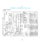
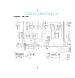
Страница 162: ...7 14 Schematic wiring diagram LXE10E 1 7 10 https daikin p ru ...
Страница 163: ...7 15 Stereoscopic wiring diagram LXE10E 1 7 11 https daikin p ru ...


