18
B. Design Requirements Unique to Horizontal Twin Pipe Venting Systems
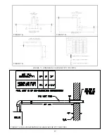
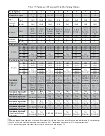
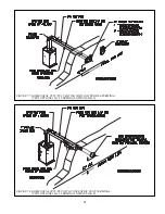
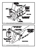
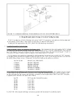
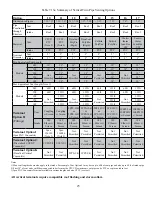
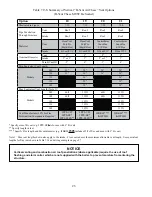
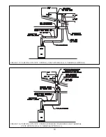
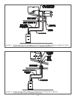
Table 7.5 summarizes all horizontal twin pipe vent options. Illustrations of horizontal twin pipe vent systems are shown in
Figures 7.6 – 7.10. In addition to the requirements in Part VII-A, observe the following design requirements:
1. Permitted
Terminals
for
Horizontal
Venting:
Terminal Option A: Fittings (Acceptable for Vent Options 1-8) – Vent terminates in a plain end (coupling for PVC, bell
&\& & ^` "'' %&'
Outer edge of both terminals must be within 10” of the wall surface (Figures 7.6, 7.9). The section of DuraVent Polypro,
"#^ *&#&
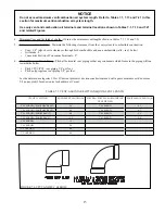
Use of rodent screens is generally recommended for both terminations. Two rodent screens suitable for 3” PVC terminals
&' ## & &#' ^ %++"" &\#
# %&_ &%&`\^&';
Size/Vent System
Rodent Screen (“Bird Guard”)
2” Polypro
DuraVent # 2PPS-BG
3” Polypro
DuraVent # 3PPS-BG
+
+^!$
!$
2” InnoFlue
Centrotherm # IASPP02
3” InnoFlue
Centrotherm # IASPP03
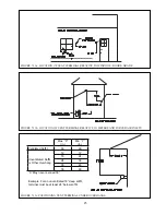
# )( &)%&\""""") & % %
on snorkels as shown in Figure 7.12. When this is done, the equivalent length of all pipe on the exterior of the building,
*# %#)\&'# %#( )%#$#* )
# ##)& % ( &\^&
snorkeled.
$ ;*}'$ _ \+` – This terminal is shown in Figure 7.7. If
the terminal is oriented vertically (alternate orientation shown in Fig 7.7) the exhaust opening must be on the top as shown.
See Part VII-E of this manual and the Ipex instructions provided with the terminal, for installation details.
$ "; ) #}'$ _ \+` – This terminal is shown in Figure
7.7. If the terminal is oriented vertically (alternate orientation shown in Fig 7.7) the exhaust opening must be on the top as
shown. See Part VII-E of this manual and the Diversitech instructions provided with the terminal, for installation details.
Terminal Option D: Ipex FGV Concentric Terminal (Acceptable for Vent Options 1,2) - This terminal is shown in Figure 7.8
and may be used with CPVC/PVC vent systems. This terminal is available in various lengths and in both PVC and CPVC.
Terminals acceptable for use with these vent options are as follows:
Ipex PN
FGV Concentric Terminal Description
196005
2 x 16” PVC
196105
2 x 28” PVC
196125
2 x 40” PVC
196006
3 x 20” PVC
196106
3 x 32” PVC
196116
3 x 44” PVC
197107
3 x 32” CPVC
197117
3 x 44” CPVC
See Part VII-E of this manual and the Ipex instructions provided with the terminal, for installation details.
Terminal Option E: Diversitech Concentric Terminal (Acceptable for Vent Options 1,2) - This terminal is shown in Figure 7.8
and may be used with CPVC/PVC vent systems. See Part VII-E of this manual and the Diversitech instructions provided with
the terminal, for installation details.
Terminal Option F: DuraVent PolyPro Concentric Terminal (Acceptable for Vent Options 3,4) - This terminal is shown in
Figure 7.10 and may be used with DuraVent 2” or 3” PolyPro vent systems. See Part VII-F of this manual and the DuraVent
instructions provided with the terminal, for installation details.
Содержание PHNTM080
Страница 2: ......
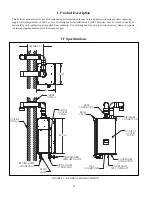
Страница 9: ...7 Figure 4 1 Minimum Clearances To Combustible Construction...
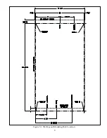
Страница 11: ...9 Figure 5 1 Wall Layout Mounting Hole Location...
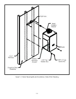
Страница 12: ...10 Figure 5 2 Boiler Mounting Bracket Installation Boiler Wall Mounting...
Страница 39: ...37 FIGURE 7 24 SPLIT VENT SYSTEM FLEX IN ABANDONED MASONRY CHIMNEY VENT OPTIONS 33 38...
Страница 63: ...61 This page is intentionally left blank...
Страница 68: ...66 FIGURE 9 2 PIPING METHOD 1 NEAR BOILER PIPING HEATING ONLY...
Страница 69: ...67 FIGURE 9 3A PIPING METHOD 1 NEAR BOILER PIPING HEATING PLUS INDIRECT WATER HEATER IWH OFF PRIMARY LOOP...
Страница 70: ...68 FIGURE 9 3B PIPING METHOD 1 NEAR BOILER PIPING HEATING PLUS INDIRECT WATER HEATER IWH OFF BOILER LOOP...
Страница 72: ...70 FIGURE 9 6 PIPING METHOD 1 NEAR BOILER PIPING SHADED BOILER LOOP...
Страница 80: ...78 FIGURE 10 2 HIGH VOLTAGE PCB TERMINAL CONNECTIONS FIGURE 10 3 LOW VOLTAGE PCB TERMINAL CONNECTIONS...
Страница 82: ...80 FIGURE 10 4 PROPER INSTALLATION OF HEADER SENSOR...
Страница 84: ...82 FIGURE 10 6 INTERNAL WIRING CONNECTIONS DIAGRAM...
Страница 85: ...83...
Страница 92: ...90 Lighting and Operating Instructions...
Страница 98: ...96 FIGURE 12 2 PIPING FOR DHW OPTIONS 1 2 ALSO SEE FIGURES 9 3A 9 3B FIGURE 12 3 PIPING FOR DHW OPTION 3...
Страница 101: ...99 FIGURE 12 5 SETTINGS MENU SEE PART C FOR ADDITIONAL INFORMATION...
Страница 113: ...111 FIGURE 13 2 IGNITION ELECTRODE GAP FIGURE 13 3 CONDENSATE TRAP EXPLODED PARTS VIEW...
Страница 125: ...123...
Страница 127: ...125 40 33 31 27 28 34 35 37 38 32 39 36 29 30 48 Blower Gas Valve Assembly for 80 100 120...
Страница 128: ...126 31 28 27 32 44 42 29 41 45 38 47 30 43 35 46 34 36 33 39 Blower Gas Valve Assembly for 150 180...
Страница 129: ...127...
Страница 131: ...129...
Страница 132: ...130...
Страница 133: ...131...
Страница 135: ...133...
Страница 137: ...135 140 141 142 143 144 145...

