24
C. Design Requirements Unique to Vertical Venting Systems
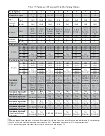
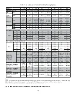
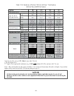
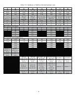
Table 7.13a summarizes all vertical twin pipe vent options. Table 7.13.b summarizes vent options in which an abandoned
B-vent chimney is used both as a chase for the vent pipe and as a conduit for combustion air.
In addition to the requirements in Part VII-A, observe the following design requirements:
1. Permitted
Terminals
for
Vertical
Venting
Terminal Option H: Fittings (Acceptable for Vent Options 10-17) – Vent terminates in a plain end (coupling for PVC, bell end
\& & ^` "' %&'_''|
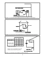
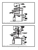
may be substituted). Observe the clearances from the roof, and normal snow line on the roof, shown in Figures 7.15 and 7.17.
$# \^*&#&
Use of rodent screens is generally recommended for both terminations. Two rodent screens suitable for 3” PVC terminals
&' ## & &#' ^ %++"" &\#
# %&_ &%&`\&^';
Size/Vent System
Rodent Screen (“Bird Guard”)
2” Polypro
DuraVent # 2PPS-BG
3” Polypro
DuraVent # 3PPS-BG
+
+^!$
!$
2” InnoFlue
Centrotherm # IASPP02
3” InnoFlue
Centrotherm # IASPP03
Terminal Option I: Ipex FGV Concentric Terminal (Acceptable for Vent Options 10 & 11) - This terminal is shown in Figure
&&' #""") # %& &' #
the Ipex instructions for this terminal. This terminal is available in various lengths and in both PVC and CPVC. Terminals
acceptable for use with these vent options are as follows:
Ipex
PN
FGV
Concentric
Terminal
Description
196005
2
x
16”
PVC
196105
2
x
28”
PVC
196125
2
x
40”
PVC
196006
3
x
20”
PVC
196106
3
x
32”
PVC
196116
3
x
44”
PVC
197107
3
x
32”
CPVC
197117
3
x
44”
CPVC
See Part VII-E of this manual and the Ipex instructions provided with the terminal, for installation details.
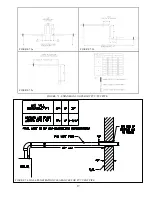
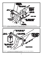
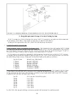
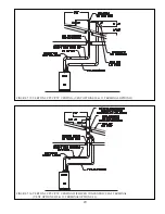
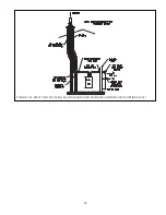
FIGURE 7.12: SNORKEL TERMINAL CONFIGURATION (CPVC/PVC VENT SYSTEMS ONLY)
Содержание PHNTM080
Страница 2: ......
Страница 9: ...7 Figure 4 1 Minimum Clearances To Combustible Construction...
Страница 11: ...9 Figure 5 1 Wall Layout Mounting Hole Location...
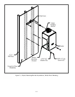
Страница 12: ...10 Figure 5 2 Boiler Mounting Bracket Installation Boiler Wall Mounting...
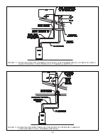
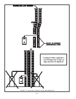
Страница 39: ...37 FIGURE 7 24 SPLIT VENT SYSTEM FLEX IN ABANDONED MASONRY CHIMNEY VENT OPTIONS 33 38...
Страница 63: ...61 This page is intentionally left blank...
Страница 68: ...66 FIGURE 9 2 PIPING METHOD 1 NEAR BOILER PIPING HEATING ONLY...
Страница 69: ...67 FIGURE 9 3A PIPING METHOD 1 NEAR BOILER PIPING HEATING PLUS INDIRECT WATER HEATER IWH OFF PRIMARY LOOP...
Страница 70: ...68 FIGURE 9 3B PIPING METHOD 1 NEAR BOILER PIPING HEATING PLUS INDIRECT WATER HEATER IWH OFF BOILER LOOP...
Страница 72: ...70 FIGURE 9 6 PIPING METHOD 1 NEAR BOILER PIPING SHADED BOILER LOOP...
Страница 80: ...78 FIGURE 10 2 HIGH VOLTAGE PCB TERMINAL CONNECTIONS FIGURE 10 3 LOW VOLTAGE PCB TERMINAL CONNECTIONS...
Страница 82: ...80 FIGURE 10 4 PROPER INSTALLATION OF HEADER SENSOR...
Страница 84: ...82 FIGURE 10 6 INTERNAL WIRING CONNECTIONS DIAGRAM...
Страница 85: ...83...
Страница 92: ...90 Lighting and Operating Instructions...
Страница 98: ...96 FIGURE 12 2 PIPING FOR DHW OPTIONS 1 2 ALSO SEE FIGURES 9 3A 9 3B FIGURE 12 3 PIPING FOR DHW OPTION 3...
Страница 101: ...99 FIGURE 12 5 SETTINGS MENU SEE PART C FOR ADDITIONAL INFORMATION...
Страница 113: ...111 FIGURE 13 2 IGNITION ELECTRODE GAP FIGURE 13 3 CONDENSATE TRAP EXPLODED PARTS VIEW...
Страница 125: ...123...
Страница 127: ...125 40 33 31 27 28 34 35 37 38 32 39 36 29 30 48 Blower Gas Valve Assembly for 80 100 120...
Страница 128: ...126 31 28 27 32 44 42 29 41 45 38 47 30 43 35 46 34 36 33 39 Blower Gas Valve Assembly for 150 180...
Страница 129: ...127...
Страница 131: ...129...
Страница 132: ...130...
Страница 133: ...131...
Страница 135: ...133...
Страница 137: ...135 140 141 142 143 144 145...

