60
J. Removing an Existing Boiler From a Common Chimney
This section only applies if this boiler is replacing an existing boiler that is being removed from a common chimney.
In some cases, when an existing boiler is removed from a common chimney, the common venting system may be too large for
the remaining appliances. At the time of removal of an existing boiler, the following steps shall be followed with each appliance
remaining connected to the common venting system placed in operation, while the other appliances remaining connected to the
common venting system are not in operation.
(a) Seal any unused openings in the common venting system.
(b) Visually inspect the venting system for proper size and horizontal pitch and determine there is no blockage or restriction,
%\ &#& '# #&&
(c) Insofar as practical, close all building doors and windows and all doors between the space in which all the appliances
remaining connected to the common venting system are located and other spaces of the building. Turn on clothes dryers and
any appliance not connected to the common venting system. Turn on any exhaust fans, such as range hoods and bathroom
*#\#' * &*#"&
(d) Place in operation the appliance being inspected. Follow the lighting instructions. Adjust thermostat so the appliance will
operate continuously.
(e) $ %#&#& % ##&\
or smoke from a cigarette, cigar, or pipe.
(f) After it has been determined that each appliance remaining connected to the common venting system properly vents when
& &)\&\' &'\*#\&&#% % #
previous condition of use.
(g) Any improper operation of the common venting system should be corrected so the installation conforms with the National
Fuel Gas Code, ANSI Z223.1. When re-sizing any portion of the common venting system, the common venting system
should be re sized to approach the minimum size as determined using the appropriate tables in Part 11 of the National Fuel
Gas Code, ANSI Z223.1.
& &|#& * \ )& ) #( [&
&|) ( (&| [&&|)
fonctionnent pas:
_` ) &&|)
_` &) &|) & %| # {( )
|(*&| \&|%\& \& & (
pourraient présenter des risques.
_` & \&¡ |¢
[&&|) &¡ #
#\ &&|) ) &|*
#& ) && |() £) *
~ ) &|^% &#
_&` | # ) &|%%#&(|
fonctionne de façon continue.
_` ^ ¢ & \& %&&£|)&&#%
&|&|#&&| %\&| %&|
_` (| & \#& & ( &\(#( &&|)
£| &&(\) \% &#
appareils au gaz à leur position originale.
_%` $) &&|) &) %&(|
~ ^"&\~¤++~^_`*&&| "~" %&|
&&|) & & \&) & ) &
* &|& ^&~ ^"&\~¤++~^_`&&&|
CAN/CSA-B149.1.
"&
A))A*?BB-
Содержание PHNTM080
Страница 2: ......
Страница 9: ...7 Figure 4 1 Minimum Clearances To Combustible Construction...
Страница 11: ...9 Figure 5 1 Wall Layout Mounting Hole Location...
Страница 12: ...10 Figure 5 2 Boiler Mounting Bracket Installation Boiler Wall Mounting...
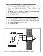
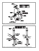
Страница 39: ...37 FIGURE 7 24 SPLIT VENT SYSTEM FLEX IN ABANDONED MASONRY CHIMNEY VENT OPTIONS 33 38...
Страница 63: ...61 This page is intentionally left blank...
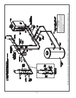
Страница 68: ...66 FIGURE 9 2 PIPING METHOD 1 NEAR BOILER PIPING HEATING ONLY...
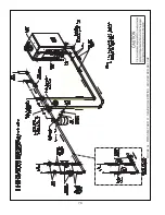
Страница 69: ...67 FIGURE 9 3A PIPING METHOD 1 NEAR BOILER PIPING HEATING PLUS INDIRECT WATER HEATER IWH OFF PRIMARY LOOP...
Страница 70: ...68 FIGURE 9 3B PIPING METHOD 1 NEAR BOILER PIPING HEATING PLUS INDIRECT WATER HEATER IWH OFF BOILER LOOP...
Страница 72: ...70 FIGURE 9 6 PIPING METHOD 1 NEAR BOILER PIPING SHADED BOILER LOOP...
Страница 80: ...78 FIGURE 10 2 HIGH VOLTAGE PCB TERMINAL CONNECTIONS FIGURE 10 3 LOW VOLTAGE PCB TERMINAL CONNECTIONS...
Страница 82: ...80 FIGURE 10 4 PROPER INSTALLATION OF HEADER SENSOR...
Страница 84: ...82 FIGURE 10 6 INTERNAL WIRING CONNECTIONS DIAGRAM...
Страница 85: ...83...
Страница 92: ...90 Lighting and Operating Instructions...
Страница 98: ...96 FIGURE 12 2 PIPING FOR DHW OPTIONS 1 2 ALSO SEE FIGURES 9 3A 9 3B FIGURE 12 3 PIPING FOR DHW OPTION 3...
Страница 101: ...99 FIGURE 12 5 SETTINGS MENU SEE PART C FOR ADDITIONAL INFORMATION...
Страница 113: ...111 FIGURE 13 2 IGNITION ELECTRODE GAP FIGURE 13 3 CONDENSATE TRAP EXPLODED PARTS VIEW...
Страница 125: ...123...
Страница 127: ...125 40 33 31 27 28 34 35 37 38 32 39 36 29 30 48 Blower Gas Valve Assembly for 80 100 120...
Страница 128: ...126 31 28 27 32 44 42 29 41 45 38 47 30 43 35 46 34 36 33 39 Blower Gas Valve Assembly for 150 180...
Страница 129: ...127...
Страница 131: ...129...
Страница 132: ...130...
Страница 133: ...131...
Страница 135: ...133...
Страница 137: ...135 140 141 142 143 144 145...


