39
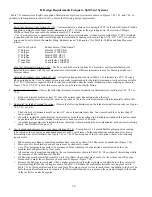
E. Assembly of CPVC/PVC Vent Systems
"&
0
"B+>-(?(((B()*(
*(@(ABB)@B,(@-
0
'%A)BI(BB?*J*ABB*
(;6%BBI"!.:ZZ7J)B)A)-
0
'%A)B?B?(@(
(A>?@(?@(?
B-
0
!((%I"!.[X4J@(%&IBB(
B*-
0
")A)(***F*-
0
AA*B?()BBB
I(Y-:YJ
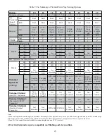
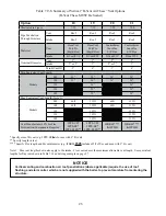
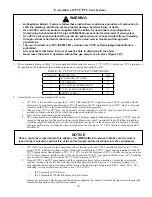
1. The components shown in Table 7.26 are supplied with this boiler for use in a 3” CPVC/PVC vent system. PVC piping must
&# # &) %&#
2. Assemble the vent system, starting at the boiler:
a. If 3” PVC is to be used for venting, the 3” CPVC elbow and the 30” straight section of CPVC provided with the
boiler must be used before transitioning to PVC. If necessary the 30” straight section of CPVC may be cut in any
location and the CPVC elbow inserted between the two resulting segments.
b. When cutting CPVC or PVC pipe, use a miter saw or a saw designed to cut PVC pipe. Use a miter box or other
method to cut pipe squarely. De-burr both the inside and outside of the cut end.
c. )
d. The vent adaptor has two different inside diameters. The larger (upper) inside diameter accepts 3” CPVC pipe and
& # _#\'\ && \^`
A locking ring in the adaptor prevents the vent pipe from coming out of the adaptor once it is inserted. Lubricate
#% #)&' #'& # "" #)&
bottoms out.
e. +"" &#)\&# "" & _`+""
using a CPVC reducing coupling or elbow. Otherwise assemble the 3” CPVC elbow and the remainder of the 30”
"" % %"" &\# "' #&#
CPVC elbow supplied with the boiler, or the end of a section of CPVC vent pipe. In the latter case, a PVC coupling
&# "# ""
f.
Clean all CPVC and PVC components with the appropriate primer before cementing. Cement the vent system
together, starting at the boiler and following the instructions provided on the cans of cement and primer. Use a
& && # &' ## %[ &_""&"`$#
following, or its equivalent, may be used to join CPVC to PVC:
Q
IPS Corporation #P-70 Primer
Q
IPS Corporation #790 Multi-Purpose Solvent Cement
' ## & % %## &' #
the instructions on the cans of primer and cement.
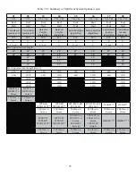
TABLE 7.26: CPVC/PVC VENT KIT COMPONENTS
QUANTITY
DESCRIPTION
SIZE
1
30” STRAIGHT CPVC PIPE
3”
1
CPVC ELBOW
3”
1
PVC COUPLING TERMINATION
3”
1
PVC 90° ELBOW TERMINATION
3”
2
RODENT SCREEN
3”
$!
$ABBB@.%$#)A-.F(
BBB@@*AB-
Содержание PHNTM080
Страница 2: ......
Страница 9: ...7 Figure 4 1 Minimum Clearances To Combustible Construction...
Страница 11: ...9 Figure 5 1 Wall Layout Mounting Hole Location...
Страница 12: ...10 Figure 5 2 Boiler Mounting Bracket Installation Boiler Wall Mounting...
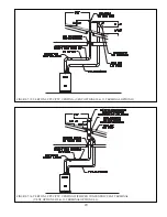
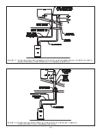
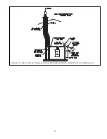
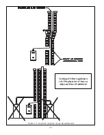
Страница 39: ...37 FIGURE 7 24 SPLIT VENT SYSTEM FLEX IN ABANDONED MASONRY CHIMNEY VENT OPTIONS 33 38...
Страница 63: ...61 This page is intentionally left blank...
Страница 68: ...66 FIGURE 9 2 PIPING METHOD 1 NEAR BOILER PIPING HEATING ONLY...
Страница 69: ...67 FIGURE 9 3A PIPING METHOD 1 NEAR BOILER PIPING HEATING PLUS INDIRECT WATER HEATER IWH OFF PRIMARY LOOP...
Страница 70: ...68 FIGURE 9 3B PIPING METHOD 1 NEAR BOILER PIPING HEATING PLUS INDIRECT WATER HEATER IWH OFF BOILER LOOP...
Страница 72: ...70 FIGURE 9 6 PIPING METHOD 1 NEAR BOILER PIPING SHADED BOILER LOOP...
Страница 80: ...78 FIGURE 10 2 HIGH VOLTAGE PCB TERMINAL CONNECTIONS FIGURE 10 3 LOW VOLTAGE PCB TERMINAL CONNECTIONS...
Страница 82: ...80 FIGURE 10 4 PROPER INSTALLATION OF HEADER SENSOR...
Страница 84: ...82 FIGURE 10 6 INTERNAL WIRING CONNECTIONS DIAGRAM...
Страница 85: ...83...
Страница 92: ...90 Lighting and Operating Instructions...
Страница 98: ...96 FIGURE 12 2 PIPING FOR DHW OPTIONS 1 2 ALSO SEE FIGURES 9 3A 9 3B FIGURE 12 3 PIPING FOR DHW OPTION 3...
Страница 101: ...99 FIGURE 12 5 SETTINGS MENU SEE PART C FOR ADDITIONAL INFORMATION...
Страница 113: ...111 FIGURE 13 2 IGNITION ELECTRODE GAP FIGURE 13 3 CONDENSATE TRAP EXPLODED PARTS VIEW...
Страница 125: ...123...
Страница 127: ...125 40 33 31 27 28 34 35 37 38 32 39 36 29 30 48 Blower Gas Valve Assembly for 80 100 120...
Страница 128: ...126 31 28 27 32 44 42 29 41 45 38 47 30 43 35 46 34 36 33 39 Blower Gas Valve Assembly for 150 180...
Страница 129: ...127...
Страница 131: ...129...
Страница 132: ...130...
Страница 133: ...131...
Страница 135: ...133...
Страница 137: ...135 140 141 142 143 144 145...

