84
XI Start-up and Checkout
"&
)B@(?()(*)B(B-
$!
B)?)?)*BA*
?*(?B `:4-49-
Use the following procedure for initial start-up of the boiler:
1) Verify
that the venting, water piping, gas piping and electrical system are installed properly.
2) " \'&% &#&#)
3) "##%))'# &%&
4) &&\##)& \*\& && )
5) Fill the boiler and hydronic system with water meeting the following requirements below (also see the note on the next page):
Q
pH between 6.5 and 9.5
Q
Hardness less than 7 grains/gallon
Q
Chlorides less than 200ppm
Q
Pressurize the system to at least 12 psi at the boiler
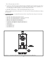
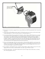
6) Bleed air from the heat exchanger using the manual air vent in the top left side of the heat exchanger (Figure 11.1). To do
this install a piece of ¼” ID clear tubing over the hose barb and route the tubing to a location where water will not damage
controls or nearby construction. Turn vent counter clockwise and allow heat exchanger to vent until a steady stream of water
is observed. Close vent and remove hose.
7) "#% %&% % #&' # #
National Fuel Gas Code
for ad-
ditional information on testing and purging gas lines.
8) ") & %
9) Inspect all wiring for loose, uninsulated or miswired connections.
"&
>-!)+)()BB(*96B76BB
)AA-A+B(-
"&
0
()@@BC)(FF-
0
.F((*))*(*)@
C))*ABD(-
Содержание PHNTM080
Страница 2: ......
Страница 9: ...7 Figure 4 1 Minimum Clearances To Combustible Construction...
Страница 11: ...9 Figure 5 1 Wall Layout Mounting Hole Location...
Страница 12: ...10 Figure 5 2 Boiler Mounting Bracket Installation Boiler Wall Mounting...
Страница 39: ...37 FIGURE 7 24 SPLIT VENT SYSTEM FLEX IN ABANDONED MASONRY CHIMNEY VENT OPTIONS 33 38...
Страница 63: ...61 This page is intentionally left blank...
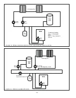
Страница 68: ...66 FIGURE 9 2 PIPING METHOD 1 NEAR BOILER PIPING HEATING ONLY...
Страница 69: ...67 FIGURE 9 3A PIPING METHOD 1 NEAR BOILER PIPING HEATING PLUS INDIRECT WATER HEATER IWH OFF PRIMARY LOOP...
Страница 70: ...68 FIGURE 9 3B PIPING METHOD 1 NEAR BOILER PIPING HEATING PLUS INDIRECT WATER HEATER IWH OFF BOILER LOOP...
Страница 72: ...70 FIGURE 9 6 PIPING METHOD 1 NEAR BOILER PIPING SHADED BOILER LOOP...
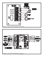
Страница 80: ...78 FIGURE 10 2 HIGH VOLTAGE PCB TERMINAL CONNECTIONS FIGURE 10 3 LOW VOLTAGE PCB TERMINAL CONNECTIONS...
Страница 82: ...80 FIGURE 10 4 PROPER INSTALLATION OF HEADER SENSOR...
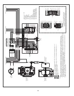
Страница 84: ...82 FIGURE 10 6 INTERNAL WIRING CONNECTIONS DIAGRAM...
Страница 85: ...83...
Страница 92: ...90 Lighting and Operating Instructions...
Страница 98: ...96 FIGURE 12 2 PIPING FOR DHW OPTIONS 1 2 ALSO SEE FIGURES 9 3A 9 3B FIGURE 12 3 PIPING FOR DHW OPTION 3...
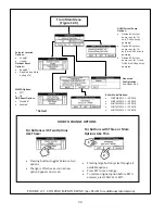
Страница 101: ...99 FIGURE 12 5 SETTINGS MENU SEE PART C FOR ADDITIONAL INFORMATION...
Страница 113: ...111 FIGURE 13 2 IGNITION ELECTRODE GAP FIGURE 13 3 CONDENSATE TRAP EXPLODED PARTS VIEW...
Страница 125: ...123...
Страница 127: ...125 40 33 31 27 28 34 35 37 38 32 39 36 29 30 48 Blower Gas Valve Assembly for 80 100 120...
Страница 128: ...126 31 28 27 32 44 42 29 41 45 38 47 30 43 35 46 34 36 33 39 Blower Gas Valve Assembly for 150 180...
Страница 129: ...127...
Страница 131: ...129...
Страница 132: ...130...
Страница 133: ...131...
Страница 135: ...133...
Страница 137: ...135 140 141 142 143 144 145...

