20
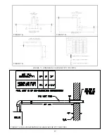
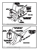
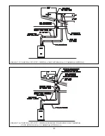
FIGURE 7.6: HORIZONTAL CPVC/PVC VENTING, (VENT OPTIONS #1 & 2, TERMINAL OPTION A)
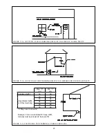
2. Horizontal Vent and Air Intake Terminal Location - Observe the following limitations on the vent terminal location (also see
Figure 7.11). When locating a concentric terminal, observe the limitations outlined below for “vent terminals”.
Q
Vent terminal must be at least 1 foot from any door, window, or gravity inlet into the building.
Q
]#$ _ %`&\ #& '# &
exhaust terminals. The recommended horizontal spacing between inlet and exhaust terminals is 36”, however this
spacing may be reduced to 12” (center-to-center) if necessary. The elevation of the exhaust terminal must be at,
or above, that of the intake terminal. The 12” minimum horizontal spacing must be maintained regardless of the
vertical separation between the intake and exhaust terminals. Both terminals must be located on the same wall.
Q
The bottom of all terminals must be at least 12” above the normal snow line. In no case should they be less than 12”
above grade level.
Q
The bottom of the vent terminal must be at least 7 feet above a public walkway.
Q
Do not install the vent terminal directly over windows or doors.
Q
The bottom of the vent terminal must be at least 3 feet above any forced air inlet located within 10 feet.
Q
USA Only: A clearance of at least 4 feet horizontally must be maintained between the vent terminal and gas meters,
electric meters, regulators, and relief equipment. Do not install vent terminal over this equipment. In Canada, refer
to B149.1 Installation Code for clearance to meters, regulators and relief equipment.
Q
Do not locate the vent terminal under decks or similar structures.
Q
$ ') &)\&#)#%#)#%
depth exceed 36”. Where permitted by the authority having jurisdiction and local experience, the terminal may be
located closer to unventilated$# ) &&#&##
Figure 7.10c for details.
Q
Vent terminal must be at least 6 feet from an inside corner.
Q
& & \' #%&\& {\[&#)
& %# #[[&%%&\##&
be moved or protected.
Q
Install the vent and air intake terminals on a wall away from the prevailing wind. Reliable operation of this boiler
cannot be guaranteed if these terminals are subjected to winds in excess of 40 mph.
Q
Air intake terminal must not terminate in areas that might contain combustion air contaminates, such as near
swimming pools. See WARNING on page 12.
Содержание PHNTM080
Страница 2: ......
Страница 9: ...7 Figure 4 1 Minimum Clearances To Combustible Construction...
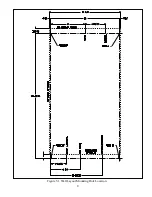
Страница 11: ...9 Figure 5 1 Wall Layout Mounting Hole Location...
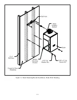
Страница 12: ...10 Figure 5 2 Boiler Mounting Bracket Installation Boiler Wall Mounting...
Страница 39: ...37 FIGURE 7 24 SPLIT VENT SYSTEM FLEX IN ABANDONED MASONRY CHIMNEY VENT OPTIONS 33 38...
Страница 63: ...61 This page is intentionally left blank...
Страница 68: ...66 FIGURE 9 2 PIPING METHOD 1 NEAR BOILER PIPING HEATING ONLY...
Страница 69: ...67 FIGURE 9 3A PIPING METHOD 1 NEAR BOILER PIPING HEATING PLUS INDIRECT WATER HEATER IWH OFF PRIMARY LOOP...
Страница 70: ...68 FIGURE 9 3B PIPING METHOD 1 NEAR BOILER PIPING HEATING PLUS INDIRECT WATER HEATER IWH OFF BOILER LOOP...
Страница 72: ...70 FIGURE 9 6 PIPING METHOD 1 NEAR BOILER PIPING SHADED BOILER LOOP...
Страница 80: ...78 FIGURE 10 2 HIGH VOLTAGE PCB TERMINAL CONNECTIONS FIGURE 10 3 LOW VOLTAGE PCB TERMINAL CONNECTIONS...
Страница 82: ...80 FIGURE 10 4 PROPER INSTALLATION OF HEADER SENSOR...
Страница 84: ...82 FIGURE 10 6 INTERNAL WIRING CONNECTIONS DIAGRAM...
Страница 85: ...83...
Страница 92: ...90 Lighting and Operating Instructions...
Страница 98: ...96 FIGURE 12 2 PIPING FOR DHW OPTIONS 1 2 ALSO SEE FIGURES 9 3A 9 3B FIGURE 12 3 PIPING FOR DHW OPTION 3...
Страница 101: ...99 FIGURE 12 5 SETTINGS MENU SEE PART C FOR ADDITIONAL INFORMATION...
Страница 113: ...111 FIGURE 13 2 IGNITION ELECTRODE GAP FIGURE 13 3 CONDENSATE TRAP EXPLODED PARTS VIEW...
Страница 125: ...123...
Страница 127: ...125 40 33 31 27 28 34 35 37 38 32 39 36 29 30 48 Blower Gas Valve Assembly for 80 100 120...
Страница 128: ...126 31 28 27 32 44 42 29 41 45 38 47 30 43 35 46 34 36 33 39 Blower Gas Valve Assembly for 150 180...
Страница 129: ...127...
Страница 131: ...129...
Страница 132: ...130...
Страница 133: ...131...
Страница 135: ...133...
Страница 137: ...135 140 141 142 143 144 145...

