119
Q
{&& &
Q
'^
Supply Sensor
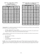
– The boiler control infers the supply temperature based on the resistance measured at the supply sensor. Table
#'# '# &# |'
temperature limit control, there are actually two “thermistors” in the supply sensor wired in parallel (Figure 10.5). The control
# #'# &) # % & '#
readings.
Return Sensor
– The boiler control infers the return temperature based on the resistance measured across a single thermistor in
the return sensor. Table 14.6a shows this resistance as a function of water temperature.
Flue Temperature Sensor
$# #%&# &#
$#'# $#'#
#' & _^ %`$## #'# &
) # % & '#& %
Outdoor Sensor
– The boiler control infers the outdoor temperature based on the resistance measured across a single thermistor
in the outdoor sensor. Table 14.6b shows this resistance as a function of temperature.
Condensate Trap
$#&'&)# '# %%#)#
this trap becomes blocked, condensate will start to back up in the trap. To prevent a rising condensate level from backing up
##*#%\#%&' &#&' &&# #'## %#
&)' && %&_^ %`$# ' #
&^ %
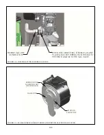
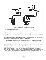
FIGURE 14.5: PRESSURE SWITCH TUBING CONNECTIONS
Содержание PHNTM080
Страница 2: ......
Страница 9: ...7 Figure 4 1 Minimum Clearances To Combustible Construction...
Страница 11: ...9 Figure 5 1 Wall Layout Mounting Hole Location...
Страница 12: ...10 Figure 5 2 Boiler Mounting Bracket Installation Boiler Wall Mounting...
Страница 39: ...37 FIGURE 7 24 SPLIT VENT SYSTEM FLEX IN ABANDONED MASONRY CHIMNEY VENT OPTIONS 33 38...
Страница 63: ...61 This page is intentionally left blank...
Страница 68: ...66 FIGURE 9 2 PIPING METHOD 1 NEAR BOILER PIPING HEATING ONLY...
Страница 69: ...67 FIGURE 9 3A PIPING METHOD 1 NEAR BOILER PIPING HEATING PLUS INDIRECT WATER HEATER IWH OFF PRIMARY LOOP...
Страница 70: ...68 FIGURE 9 3B PIPING METHOD 1 NEAR BOILER PIPING HEATING PLUS INDIRECT WATER HEATER IWH OFF BOILER LOOP...
Страница 72: ...70 FIGURE 9 6 PIPING METHOD 1 NEAR BOILER PIPING SHADED BOILER LOOP...
Страница 80: ...78 FIGURE 10 2 HIGH VOLTAGE PCB TERMINAL CONNECTIONS FIGURE 10 3 LOW VOLTAGE PCB TERMINAL CONNECTIONS...
Страница 82: ...80 FIGURE 10 4 PROPER INSTALLATION OF HEADER SENSOR...
Страница 84: ...82 FIGURE 10 6 INTERNAL WIRING CONNECTIONS DIAGRAM...
Страница 85: ...83...
Страница 92: ...90 Lighting and Operating Instructions...
Страница 98: ...96 FIGURE 12 2 PIPING FOR DHW OPTIONS 1 2 ALSO SEE FIGURES 9 3A 9 3B FIGURE 12 3 PIPING FOR DHW OPTION 3...
Страница 101: ...99 FIGURE 12 5 SETTINGS MENU SEE PART C FOR ADDITIONAL INFORMATION...
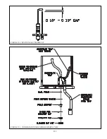
Страница 113: ...111 FIGURE 13 2 IGNITION ELECTRODE GAP FIGURE 13 3 CONDENSATE TRAP EXPLODED PARTS VIEW...
Страница 125: ...123...
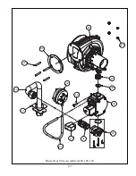
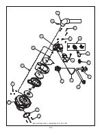
Страница 127: ...125 40 33 31 27 28 34 35 37 38 32 39 36 29 30 48 Blower Gas Valve Assembly for 80 100 120...
Страница 128: ...126 31 28 27 32 44 42 29 41 45 38 47 30 43 35 46 34 36 33 39 Blower Gas Valve Assembly for 150 180...
Страница 129: ...127...
Страница 131: ...129...
Страница 132: ...130...
Страница 133: ...131...
Страница 135: ...133...
Страница 137: ...135 140 141 142 143 144 145...

