94
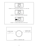
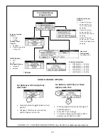
ForButtonswithTwoOptions
LikeThese:
x
Pressingbuttonstogglesbetweentwo
options.
x
Changeiseffectiveassoonasnew
optionappearsonscreen.
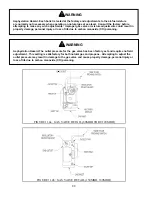
ForButtonswithThreeorMore
OptionsLikeThis:
x
Pressinglargebuttoncyclesthroughall
availableoptions.
x
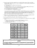
PressSETtosavechange
x
TorestoreoriginaloptionbeforeSETis
pressed,pressCANCELorEXIT.
1
2
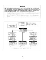
HOWTOCHANGEOPTIONS
FromMainMenu
(Figure12.0)
BoilerModelOptions:
x
PHNTM080(S.L.–2000ft)
x
PHNTM100(S.L.–2000ft)
x
PHNTM120(S.L.–2000ft)
x
PHNTM150(S.L.–2000ft)
x
PHNTM180(S.L.–2000ft)
DHW/SystemPump
Options:
x
Option#1:System
pumprunsforCH
only,DHWpriority
pumping*
x
Option#2:System
pumprunsforCH
only,NoDHWpriority
pumping
x
Option#3:System
pumprunsforCHand
DHW,NoDHWpriority
pumping.
SetpointLocation
Options:
x
Supply*
x
Header
OutdoorReset
Options:
x
Enabled*
x
Disabled(seeNote
onPage73)
WWSDOptions:
x
Off*
x
On
ODRBoostOptions:
x
Disabled*
x
Enabled
*Default
Advanced
Configuration:
SeeAppendixA.
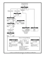
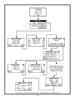
FIGURE 12.1: CONFIGURATION MENU (See Part B for additional information)
Содержание PHNTM080
Страница 2: ......
Страница 9: ...7 Figure 4 1 Minimum Clearances To Combustible Construction...
Страница 11: ...9 Figure 5 1 Wall Layout Mounting Hole Location...
Страница 12: ...10 Figure 5 2 Boiler Mounting Bracket Installation Boiler Wall Mounting...
Страница 39: ...37 FIGURE 7 24 SPLIT VENT SYSTEM FLEX IN ABANDONED MASONRY CHIMNEY VENT OPTIONS 33 38...
Страница 63: ...61 This page is intentionally left blank...
Страница 68: ...66 FIGURE 9 2 PIPING METHOD 1 NEAR BOILER PIPING HEATING ONLY...
Страница 69: ...67 FIGURE 9 3A PIPING METHOD 1 NEAR BOILER PIPING HEATING PLUS INDIRECT WATER HEATER IWH OFF PRIMARY LOOP...
Страница 70: ...68 FIGURE 9 3B PIPING METHOD 1 NEAR BOILER PIPING HEATING PLUS INDIRECT WATER HEATER IWH OFF BOILER LOOP...
Страница 72: ...70 FIGURE 9 6 PIPING METHOD 1 NEAR BOILER PIPING SHADED BOILER LOOP...
Страница 80: ...78 FIGURE 10 2 HIGH VOLTAGE PCB TERMINAL CONNECTIONS FIGURE 10 3 LOW VOLTAGE PCB TERMINAL CONNECTIONS...
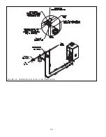
Страница 82: ...80 FIGURE 10 4 PROPER INSTALLATION OF HEADER SENSOR...
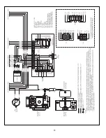
Страница 84: ...82 FIGURE 10 6 INTERNAL WIRING CONNECTIONS DIAGRAM...
Страница 85: ...83...
Страница 92: ...90 Lighting and Operating Instructions...
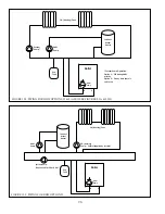
Страница 98: ...96 FIGURE 12 2 PIPING FOR DHW OPTIONS 1 2 ALSO SEE FIGURES 9 3A 9 3B FIGURE 12 3 PIPING FOR DHW OPTION 3...
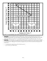
Страница 101: ...99 FIGURE 12 5 SETTINGS MENU SEE PART C FOR ADDITIONAL INFORMATION...
Страница 113: ...111 FIGURE 13 2 IGNITION ELECTRODE GAP FIGURE 13 3 CONDENSATE TRAP EXPLODED PARTS VIEW...
Страница 125: ...123...
Страница 127: ...125 40 33 31 27 28 34 35 37 38 32 39 36 29 30 48 Blower Gas Valve Assembly for 80 100 120...
Страница 128: ...126 31 28 27 32 44 42 29 41 45 38 47 30 43 35 46 34 36 33 39 Blower Gas Valve Assembly for 150 180...
Страница 129: ...127...
Страница 131: ...129...
Страница 132: ...130...
Страница 133: ...131...
Страница 135: ...133...
Страница 137: ...135 140 141 142 143 144 145...

