56
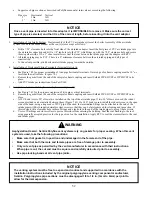
3. Installation of Air Intake System - Start assembly of the PVC air intake system at the boiler. Assembly of the air intake
system is done in the same manner as the vent system except as follows:
a. +# # &# &# "
into the air intake connection and drill a 1/8” tap hole into the PVC which lines up with the 7/32” clearance hole and
secure them together with a #10 x 1” sheet metal screw. Seal the joint between the intake pipe and the adaptor with
RTV.
b. All intake piping may be PVC.
c. There is a 0” minimum clearance between the air intake piping and all types of construction.
d. To the extent possible, pitch horizontal air intake piping towards the outside.
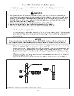
4. Installation of Horizontal Fitting Terminals (Terminal Option A):
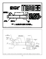
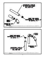
a. See Figure 7.45 for proper orientation of twin pipe horizontal terminals. Outer edge of end pipe must be 10” or less
from the wall surface. (Figure 7.5)
b. Use plain end UV stabilized Centrotherm 2” pipe # ISEP02 or ISEP0239 or 3” pipe # ISEP03 or ISEP0339 and
insert Centrotherm Bird Screen #IASPP02 or #IASPP03 in the end of the pipe.
c. Add PVC intake per instructions from Part VII-F.
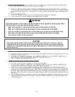
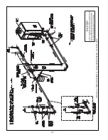
5. Installation of Vertical Fitting Terminals (Terminal Option H):
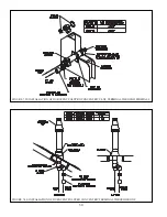
a. See Figure 7.46
for the proper orientation of twin pipe vertical terminals.
b. Use plain end UV stabilized Centrotherm 2” pipe # ISEP02 or ISEP0239 or 3” pipe # ISEP03 or ISEP0339 and
insert Centrotherm Bird Screen #IASPP02 or #IASPP03 in the end of the pipe.
c. A 180° bend (or two 90° elbows) are installed on the top of the air intake pipe. If two 90° elbows are used, the
rodent screen provided can be installed between them (Figure 7.46). If a 180° bend is used, install the rodent screen
# &#&\ % %&" & &\# %#&#
&# ' #& & '##)& %&
# &\& # # %&# #&#
these screws.
d. # %&) %# & %## %#
using generally accepted practice for the type of roof on the installation. Apply RTV to seal the storm collars to the
vent and intake pipes.
"&
"B+>-))*)FBB-
A)(@F?B(/
0
.F(FB())BB-
0
.F(*))BB)B)*-
0
$(ABBB)*A)((?(-
BB(@()(*D((*(B)*-
0
'ABB,-
$!
!A))(*+B(BB?
((*BBBA)B)((@
)-%BBBB)(*4<;-I7))JB,?
)+B-
Содержание PHNTM080
Страница 2: ......
Страница 9: ...7 Figure 4 1 Minimum Clearances To Combustible Construction...
Страница 11: ...9 Figure 5 1 Wall Layout Mounting Hole Location...
Страница 12: ...10 Figure 5 2 Boiler Mounting Bracket Installation Boiler Wall Mounting...
Страница 39: ...37 FIGURE 7 24 SPLIT VENT SYSTEM FLEX IN ABANDONED MASONRY CHIMNEY VENT OPTIONS 33 38...
Страница 63: ...61 This page is intentionally left blank...
Страница 68: ...66 FIGURE 9 2 PIPING METHOD 1 NEAR BOILER PIPING HEATING ONLY...
Страница 69: ...67 FIGURE 9 3A PIPING METHOD 1 NEAR BOILER PIPING HEATING PLUS INDIRECT WATER HEATER IWH OFF PRIMARY LOOP...
Страница 70: ...68 FIGURE 9 3B PIPING METHOD 1 NEAR BOILER PIPING HEATING PLUS INDIRECT WATER HEATER IWH OFF BOILER LOOP...
Страница 72: ...70 FIGURE 9 6 PIPING METHOD 1 NEAR BOILER PIPING SHADED BOILER LOOP...
Страница 80: ...78 FIGURE 10 2 HIGH VOLTAGE PCB TERMINAL CONNECTIONS FIGURE 10 3 LOW VOLTAGE PCB TERMINAL CONNECTIONS...
Страница 82: ...80 FIGURE 10 4 PROPER INSTALLATION OF HEADER SENSOR...
Страница 84: ...82 FIGURE 10 6 INTERNAL WIRING CONNECTIONS DIAGRAM...
Страница 85: ...83...
Страница 92: ...90 Lighting and Operating Instructions...
Страница 98: ...96 FIGURE 12 2 PIPING FOR DHW OPTIONS 1 2 ALSO SEE FIGURES 9 3A 9 3B FIGURE 12 3 PIPING FOR DHW OPTION 3...
Страница 101: ...99 FIGURE 12 5 SETTINGS MENU SEE PART C FOR ADDITIONAL INFORMATION...
Страница 113: ...111 FIGURE 13 2 IGNITION ELECTRODE GAP FIGURE 13 3 CONDENSATE TRAP EXPLODED PARTS VIEW...
Страница 125: ...123...
Страница 127: ...125 40 33 31 27 28 34 35 37 38 32 39 36 29 30 48 Blower Gas Valve Assembly for 80 100 120...
Страница 128: ...126 31 28 27 32 44 42 29 41 45 38 47 30 43 35 46 34 36 33 39 Blower Gas Valve Assembly for 150 180...
Страница 129: ...127...
Страница 131: ...129...
Страница 132: ...130...
Страница 133: ...131...
Страница 135: ...133...
Страница 137: ...135 140 141 142 143 144 145...

