137
# %&~% &'+# & #
instructions if either, or both, of the following are true:
Q
&' #}%
Q
& &)+
Follow steps 1-13 below in the order they are presented.
Steps applying to only one type of conversion (LP or altitude) may
be skipped if that type of conversion is not being performed.
1) If not already done, install the boiler in accordance with this manual, following all instructions in Part XI (Start-up and
Check-out) up to Step 10.
2) LP CONVERSIONS ONLY – Set the throttle to its preliminary setting for LP. To do this:
a. Turn the throttle (Figure A.1) clockwise until it stops (several full turns).
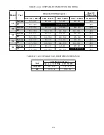
b. Turn throttle counter-clockwise the exact number of turns shown in Table A.2.
3) ALTITUDE CONVERSIONS ONLY – Control system must be set to permit operation at higher fan speeds than those used
at sea level. This is changed in the ALTITUDE MENU (Figure A.3). To change altitude setting in control:
a. From the home screen, press MENU
b. From the main menu, press CONFIGURE
c. When prompted for a password. Use the “+1” button to raise the password to 5, then press SUBMIT. If you
accidentally raise the password above 5, press EXIT to return to the main menu and start over.
& #'& &\) '#]~~&""$##%
#% \~"##&)&%
f.
Press ALTITUDE. Review the WARNING screen that follows, and press ACCEPT to reach the altitude screen.
g. Press the altitude shown to advance to the appropriate altitude (Figure A.3). Four altitude ranges can be selected:
Q
+_`
Q
+
Q
Q
+
Where the installation altitude is very close to one of these breakpoints, use the lower range.
# $# % "#&# #%'#$&# &
# %
i.
Return to the HOME screen and verify that the appropriate altitude range (in kft) is shown in the lower right corner
of
the
screen
(Fig
A.3)
` # %# %# % &%# & %##
for ignition, allow to boiler to make at least four more attempts to light. If boiler still does not light, turn the throttle
counterclockwise in 1/8 turn increments, allowing the boiler to make at least four tries for ignition at each setting, until the
boiler
lights.
` # %#\## %# %# %\& %\#! %#
Fire Hold as described in Part XI (start-up and checkout). Allow the boiler to operate for approximately 5 minutes before
% & %~;#+ \&# &# %##&
The boiler will also be released from manual input if the user manually navigates back to the home screen.
` \ %&# ##)&
` ]# # # %#&[##&& #"+ %#' #$;
Q
$&#"+_ #+`##'
Q
$ #"+_&#+`##'
Make adjustments in increments of 1/8 to 1/4 turn and allow the boiler at least a minute to respond to each adjustment before
making another. In general, the CO level will be at its lowest somewhere in the CO2 range shown in this table. Consult
Содержание PHNTM080
Страница 2: ......
Страница 9: ...7 Figure 4 1 Minimum Clearances To Combustible Construction...
Страница 11: ...9 Figure 5 1 Wall Layout Mounting Hole Location...
Страница 12: ...10 Figure 5 2 Boiler Mounting Bracket Installation Boiler Wall Mounting...
Страница 39: ...37 FIGURE 7 24 SPLIT VENT SYSTEM FLEX IN ABANDONED MASONRY CHIMNEY VENT OPTIONS 33 38...
Страница 63: ...61 This page is intentionally left blank...
Страница 68: ...66 FIGURE 9 2 PIPING METHOD 1 NEAR BOILER PIPING HEATING ONLY...
Страница 69: ...67 FIGURE 9 3A PIPING METHOD 1 NEAR BOILER PIPING HEATING PLUS INDIRECT WATER HEATER IWH OFF PRIMARY LOOP...
Страница 70: ...68 FIGURE 9 3B PIPING METHOD 1 NEAR BOILER PIPING HEATING PLUS INDIRECT WATER HEATER IWH OFF BOILER LOOP...
Страница 72: ...70 FIGURE 9 6 PIPING METHOD 1 NEAR BOILER PIPING SHADED BOILER LOOP...
Страница 80: ...78 FIGURE 10 2 HIGH VOLTAGE PCB TERMINAL CONNECTIONS FIGURE 10 3 LOW VOLTAGE PCB TERMINAL CONNECTIONS...
Страница 82: ...80 FIGURE 10 4 PROPER INSTALLATION OF HEADER SENSOR...
Страница 84: ...82 FIGURE 10 6 INTERNAL WIRING CONNECTIONS DIAGRAM...
Страница 85: ...83...
Страница 92: ...90 Lighting and Operating Instructions...
Страница 98: ...96 FIGURE 12 2 PIPING FOR DHW OPTIONS 1 2 ALSO SEE FIGURES 9 3A 9 3B FIGURE 12 3 PIPING FOR DHW OPTION 3...
Страница 101: ...99 FIGURE 12 5 SETTINGS MENU SEE PART C FOR ADDITIONAL INFORMATION...
Страница 113: ...111 FIGURE 13 2 IGNITION ELECTRODE GAP FIGURE 13 3 CONDENSATE TRAP EXPLODED PARTS VIEW...
Страница 125: ...123...
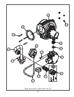
Страница 127: ...125 40 33 31 27 28 34 35 37 38 32 39 36 29 30 48 Blower Gas Valve Assembly for 80 100 120...
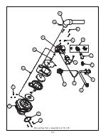
Страница 128: ...126 31 28 27 32 44 42 29 41 45 38 47 30 43 35 46 34 36 33 39 Blower Gas Valve Assembly for 150 180...
Страница 129: ...127...
Страница 131: ...129...
Страница 132: ...130...
Страница 133: ...131...
Страница 135: ...133...
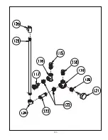
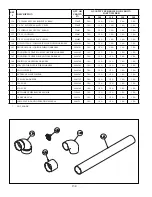
Страница 137: ...135 140 141 142 143 144 145...

