95
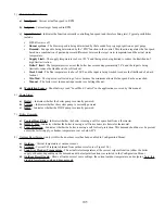
Option #1 (DEFAULT): System Pump Used for CH Only, DHW Priority Pumping
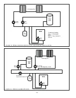
– An example of this system is shown
in Figure 12.2, as well as in Figures 9.3A and 9.3B. When this option is selected, the system operates as follows:
a) Boiler pump runs whenever there is a demand
b) DHW pump circulates water through the portion of the system loop where the boiler loop is connected (i.e. the closely
spaced tees for the boiler loop).
c) The system pump is used only to circulate water through the heating (CH) zone/s.
d) The system pump is not allowed to operate while the boiler is responding to a call for DHW (this strategy permits the
entire output of the boiler to be directed to the indirect water heater and in some cases is also needed to protect some
types of radiation from excessive temperatures).
Option #2: System Pump Used for CH Only, No DHW Priority Pumping
– An example of this system is shown in Figure
12.2, as well as in Figures 9.3A and 9.3B. The only difference between Option #2 and Option #1 is that Option #2 permits the
system circulator to operate at the same time as the DHW pump when there is a call for both heat and DHW.
Option #3: System Pump Used for Both CH and DHW, No DHW Priority Pumping
– An example of this system is
shown in Figure 12.3, When this option is selected, the system operates as follows:
a) Boiler pump runs whenever there is a demand.
b) DHW circulates water only as far as a set of closely spaced tees in the system loop.
c) The system pump is required to circulate water for either a space heating or DHW demand.
d) A fourth pump (controlled by an installer supplied relay) is required to circulate water through the radiation.
$#%#!]% \#% %#& & #& &&
#&]## #%&\# ' #]##& &% #&\$
]## #% &#\#' # %$#"%
Menu.
"&
(>-)B(A4:7_(B,((-
*@)F*-!*
)?)B(-
0
')))*?)((
)B(-
0
",()B??)((E
(-
0
BAD(*?)((
-
0
)B?*-
"'!$
&)D()(?*(BB)B(D(
)-()*)*+A?)B(-
$Bt:$Bt9(?(/
0
!)B?)B(D(
)B(-
0
"+@())+AA@())B(
?)-
0
$Bt9( (BB)?B()B<
(-
Содержание PHNTM080
Страница 2: ......
Страница 9: ...7 Figure 4 1 Minimum Clearances To Combustible Construction...
Страница 11: ...9 Figure 5 1 Wall Layout Mounting Hole Location...
Страница 12: ...10 Figure 5 2 Boiler Mounting Bracket Installation Boiler Wall Mounting...
Страница 39: ...37 FIGURE 7 24 SPLIT VENT SYSTEM FLEX IN ABANDONED MASONRY CHIMNEY VENT OPTIONS 33 38...
Страница 63: ...61 This page is intentionally left blank...
Страница 68: ...66 FIGURE 9 2 PIPING METHOD 1 NEAR BOILER PIPING HEATING ONLY...
Страница 69: ...67 FIGURE 9 3A PIPING METHOD 1 NEAR BOILER PIPING HEATING PLUS INDIRECT WATER HEATER IWH OFF PRIMARY LOOP...
Страница 70: ...68 FIGURE 9 3B PIPING METHOD 1 NEAR BOILER PIPING HEATING PLUS INDIRECT WATER HEATER IWH OFF BOILER LOOP...
Страница 72: ...70 FIGURE 9 6 PIPING METHOD 1 NEAR BOILER PIPING SHADED BOILER LOOP...
Страница 80: ...78 FIGURE 10 2 HIGH VOLTAGE PCB TERMINAL CONNECTIONS FIGURE 10 3 LOW VOLTAGE PCB TERMINAL CONNECTIONS...
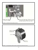
Страница 82: ...80 FIGURE 10 4 PROPER INSTALLATION OF HEADER SENSOR...
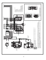
Страница 84: ...82 FIGURE 10 6 INTERNAL WIRING CONNECTIONS DIAGRAM...
Страница 85: ...83...
Страница 92: ...90 Lighting and Operating Instructions...
Страница 98: ...96 FIGURE 12 2 PIPING FOR DHW OPTIONS 1 2 ALSO SEE FIGURES 9 3A 9 3B FIGURE 12 3 PIPING FOR DHW OPTION 3...
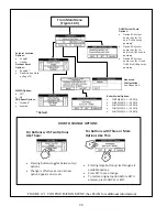
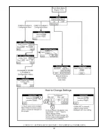
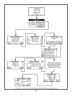
Страница 101: ...99 FIGURE 12 5 SETTINGS MENU SEE PART C FOR ADDITIONAL INFORMATION...
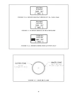
Страница 113: ...111 FIGURE 13 2 IGNITION ELECTRODE GAP FIGURE 13 3 CONDENSATE TRAP EXPLODED PARTS VIEW...
Страница 125: ...123...
Страница 127: ...125 40 33 31 27 28 34 35 37 38 32 39 36 29 30 48 Blower Gas Valve Assembly for 80 100 120...
Страница 128: ...126 31 28 27 32 44 42 29 41 45 38 47 30 43 35 46 34 36 33 39 Blower Gas Valve Assembly for 150 180...
Страница 129: ...127...
Страница 131: ...129...
Страница 132: ...130...
Страница 133: ...131...
Страница 135: ...133...
Страница 137: ...135 140 141 142 143 144 145...


