98
C. Changing Settings
# %#% & # # %#'On a new instal-
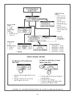
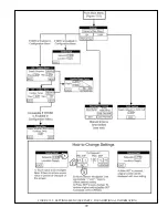
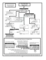
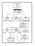
%# \#%# %A map of the Settings Menu structure is shown in Figure 12.5. To
change settings:
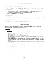
1) From the Home Screen (shown in Figure 12.0) , press “MENU” to enter the Main Menu:
a) Press
“SETTINGS”
b) When prompted for a password, use the “+1” key to raise the password to “005”. Press SUBMIT, then NEXT (if you
accidently scroll past 005, press EXIT to return to the main menu and start over).
c) Review the Warning and press ACCEPT to continue to the Settings Menu.
d) ~;%#"% # %' # %#!\'
have to reenter a password.
2) CH Settings - Press CH to change the target supply water temperature setting.
a) If outdoor reset is disabled, only one CH setpoint exists. The boiler will always attempt to maintain this temperature
during a call for CH. To change the setting, touch the button containing the current setting. Adjust the temperature using
the “+” and “-” arrows shown and press SET to save the change (also see “How to Change Settings” in Figure 12.5).
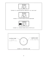
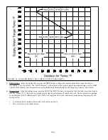
b) If outdoor reset is enabled, there are a total of four settings that can be changed (also see Figures12.5 and 12.6):
+
Max Supply Setpoint
- This is the maximum permissible supply setpoint temperature, regardless of how low the
outdoor temperature is.
+
Min Supply Setpoint
- This is the minimum permissible supply setpoint, regardless of how high the outdoor
temperature is.
+
Max Outdoor Temp
- At or above this setting, supply setpoint is equal to the “Min Supply Setpoint”
+
Min Outdoor Temp
- At or below this setting, supply setpoint is equal to the “Max Supply Setpoint”
Pressing the GRAPH button on either the CH Outdoor Reset -1 or CH Outdoor Reset -2 screen allows any of the above
four outdoor reset settings to be changed while viewing the other three. This graph is for reference only - it does not scale
with changes to the ODR settings.
c) If Warm Weather Shut-Down (WWSD) is enabled, a NEXT button will be present on the CH-Outdoor Reset - 2 screen.
This screen allows the user to set the
WWSD Outdoor Temperature
. This is the outdoor temperature above which the
boiler will ignore a call for heat from the thermostat.
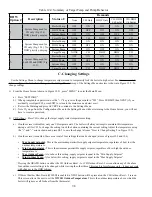
Table 12.4: Summary of Target Temp and Pump Behavior
DHW
Option #
Description
Status of:
Demands
None
CH Only
DHW Only
CH+DHW
(<60 min)
CH+DHW
(>60 min)
1
System Pump used for
CH only (Fig. 12.2).
DHW priority pumping.
Boiler Pump
OFF
ON
ON
ON
ON
DHW Pump
OFF
OFF
ON
ON
OFF
System Pump
OFF
ON
OFF
OFF
ON
Target Temp
NONE
CH
DHW
DHW
CH
2
System Pump used for
CH only (Fig. 12.2). No
DHW priority pumping.
Boiler Pump
OFF
ON
ON
ON
ON
DHW Pump
OFF
OFF
ON
ON
ON
System Pump
OFF
ON
OFF
ON
ON
Target Temp
NONE
CH
DHW
DHW
CH
3
System Pump used for
both CH and DHW (Fig.
12.3).
Boiler Pump
OFF
ON
ON
ON
ON
DHW Pump
OFF
OFF
ON
ON
OFF
System Pump
OFF
ON
ON
ON
ON
Target Temp
NONE
CH
DHW
DHW
CH
Содержание PHNTM080
Страница 2: ......
Страница 9: ...7 Figure 4 1 Minimum Clearances To Combustible Construction...
Страница 11: ...9 Figure 5 1 Wall Layout Mounting Hole Location...
Страница 12: ...10 Figure 5 2 Boiler Mounting Bracket Installation Boiler Wall Mounting...
Страница 39: ...37 FIGURE 7 24 SPLIT VENT SYSTEM FLEX IN ABANDONED MASONRY CHIMNEY VENT OPTIONS 33 38...
Страница 63: ...61 This page is intentionally left blank...
Страница 68: ...66 FIGURE 9 2 PIPING METHOD 1 NEAR BOILER PIPING HEATING ONLY...
Страница 69: ...67 FIGURE 9 3A PIPING METHOD 1 NEAR BOILER PIPING HEATING PLUS INDIRECT WATER HEATER IWH OFF PRIMARY LOOP...
Страница 70: ...68 FIGURE 9 3B PIPING METHOD 1 NEAR BOILER PIPING HEATING PLUS INDIRECT WATER HEATER IWH OFF BOILER LOOP...
Страница 72: ...70 FIGURE 9 6 PIPING METHOD 1 NEAR BOILER PIPING SHADED BOILER LOOP...
Страница 80: ...78 FIGURE 10 2 HIGH VOLTAGE PCB TERMINAL CONNECTIONS FIGURE 10 3 LOW VOLTAGE PCB TERMINAL CONNECTIONS...
Страница 82: ...80 FIGURE 10 4 PROPER INSTALLATION OF HEADER SENSOR...
Страница 84: ...82 FIGURE 10 6 INTERNAL WIRING CONNECTIONS DIAGRAM...
Страница 85: ...83...
Страница 92: ...90 Lighting and Operating Instructions...
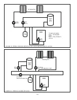
Страница 98: ...96 FIGURE 12 2 PIPING FOR DHW OPTIONS 1 2 ALSO SEE FIGURES 9 3A 9 3B FIGURE 12 3 PIPING FOR DHW OPTION 3...
Страница 101: ...99 FIGURE 12 5 SETTINGS MENU SEE PART C FOR ADDITIONAL INFORMATION...
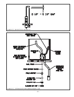
Страница 113: ...111 FIGURE 13 2 IGNITION ELECTRODE GAP FIGURE 13 3 CONDENSATE TRAP EXPLODED PARTS VIEW...
Страница 125: ...123...
Страница 127: ...125 40 33 31 27 28 34 35 37 38 32 39 36 29 30 48 Blower Gas Valve Assembly for 80 100 120...
Страница 128: ...126 31 28 27 32 44 42 29 41 45 38 47 30 43 35 46 34 36 33 39 Blower Gas Valve Assembly for 150 180...
Страница 129: ...127...
Страница 131: ...129...
Страница 132: ...130...
Страница 133: ...131...
Страница 135: ...133...
Страница 137: ...135 140 141 142 143 144 145...


