120
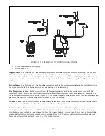
Combustion Fan
$# # * #&#&# '& # %
rate. There are two electrical connections at this fan:
Q
+% +"'#^
Q
&"%
- Delivers a PWM (speed control) signal from the boiler control to the fan. This plug also includes
`
tachometer connections so that the boiler control can monitor the actual fan speed.
In the event that there is 120volts at the boiler, but no signal at the speed control plug, this fan will run at its maximum speed.
# &;
Q
&&%
Q
'+
Q
}¬+%
Q
}%_ &')%"`
Q
}}+}%
Gas Valve
– The gas valve used on this boiler has either one or two 24VDC coils (the gas valve used on all boiler models is
&&`$#%))# +" & &'#%))&#
' %##\&+&_^ %`$# #%))% #&
180.
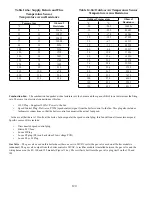
Table 14.6a: Supply, Return and Flue
Temperature Sensor
Temperature versus Resistance
Temperature
Ohms of
Resistance
°F
°C
32
0
32624
50
10
19897
68
20
12493
77
25
10000
86
30
8056
104
40
5324
122
50
3599
140
60
2483
158
70
1748
176
80
1252
194
90
912
212
100
674
230
110
506
248
120
384
Table 14.6b: Outdoor Air Temperature Sensor
Temperature versus Resistance
Outdoor Temperature
Ohms of
Resistance
°F
°C
-20
-28.9
106926
-10
-23.3
80485
0
-17.8
61246
10
-12.2
47092
20
-6.7
36519
30
-1.1
28558
40
4.4
22537
50
10.0
17926
60
15.6
14356
70
21.1
11578
76
24.4
10210
78
25.6
9795
80
26.7
9398
90
32.2
7672
100
37.8
6301
110
43.3
5203
120
48.9
4317
Содержание PHNTM080
Страница 2: ......
Страница 9: ...7 Figure 4 1 Minimum Clearances To Combustible Construction...
Страница 11: ...9 Figure 5 1 Wall Layout Mounting Hole Location...
Страница 12: ...10 Figure 5 2 Boiler Mounting Bracket Installation Boiler Wall Mounting...
Страница 39: ...37 FIGURE 7 24 SPLIT VENT SYSTEM FLEX IN ABANDONED MASONRY CHIMNEY VENT OPTIONS 33 38...
Страница 63: ...61 This page is intentionally left blank...
Страница 68: ...66 FIGURE 9 2 PIPING METHOD 1 NEAR BOILER PIPING HEATING ONLY...
Страница 69: ...67 FIGURE 9 3A PIPING METHOD 1 NEAR BOILER PIPING HEATING PLUS INDIRECT WATER HEATER IWH OFF PRIMARY LOOP...
Страница 70: ...68 FIGURE 9 3B PIPING METHOD 1 NEAR BOILER PIPING HEATING PLUS INDIRECT WATER HEATER IWH OFF BOILER LOOP...
Страница 72: ...70 FIGURE 9 6 PIPING METHOD 1 NEAR BOILER PIPING SHADED BOILER LOOP...
Страница 80: ...78 FIGURE 10 2 HIGH VOLTAGE PCB TERMINAL CONNECTIONS FIGURE 10 3 LOW VOLTAGE PCB TERMINAL CONNECTIONS...
Страница 82: ...80 FIGURE 10 4 PROPER INSTALLATION OF HEADER SENSOR...
Страница 84: ...82 FIGURE 10 6 INTERNAL WIRING CONNECTIONS DIAGRAM...
Страница 85: ...83...
Страница 92: ...90 Lighting and Operating Instructions...
Страница 98: ...96 FIGURE 12 2 PIPING FOR DHW OPTIONS 1 2 ALSO SEE FIGURES 9 3A 9 3B FIGURE 12 3 PIPING FOR DHW OPTION 3...
Страница 101: ...99 FIGURE 12 5 SETTINGS MENU SEE PART C FOR ADDITIONAL INFORMATION...
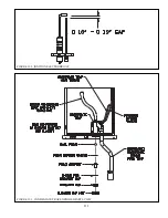
Страница 113: ...111 FIGURE 13 2 IGNITION ELECTRODE GAP FIGURE 13 3 CONDENSATE TRAP EXPLODED PARTS VIEW...
Страница 125: ...123...
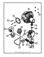
Страница 127: ...125 40 33 31 27 28 34 35 37 38 32 39 36 29 30 48 Blower Gas Valve Assembly for 80 100 120...
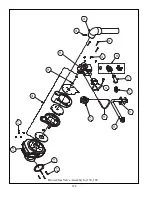
Страница 128: ...126 31 28 27 32 44 42 29 41 45 38 47 30 43 35 46 34 36 33 39 Blower Gas Valve Assembly for 150 180...
Страница 129: ...127...
Страница 131: ...129...
Страница 132: ...130...
Страница 133: ...131...
Страница 135: ...133...
Страница 137: ...135 140 141 142 143 144 145...

