118
Air Proving Switch (APS)
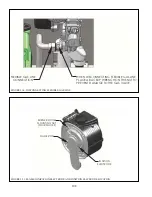
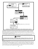
– This pressure switch is normally open and is connected to the outlet tapping on the gas valve as
shown in Figure 14.5. During pre-purge, when the gas valve is closed, the IAS is monitoring the pressure drop across gas-air
*_) #+\' #&` '#%## *# & %
to increase. The APS is calibrated to close when this pressure rises to 1.05 +/- 0.05” wc, which is a pressure at pre-purge
& %&( '#%))\# ' &){\%&#
'#%## ^# \# %&%#)##
#\# ' #) ## &#&( '
If the APS opens, look for the following:
Q
% #)
Q
&\&
Flow Switch
$#&&'' # &''* +$# ' #
intended to do two things:
Q
)## ' # _''# ' #`
Q
)## %#'#&#'
temperatures entering and exiting the heat exchanger.
$# '( && % )+_$`$# ) ##
&('#%## %# #%## ¦#'' ###
& $# # %'## *&^&#
goes into a soft lockout if the rise reaches 63F.
#'' #&\#' %;
Q
~' #
Q
$& # #&'* # )#' ^ %
11.1 when it is opened.
Q
)& %
Q
^& %
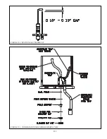
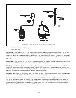
FIGURE 14.4: CONTROLS LOCATION
COMBUSTION FAN
PUMP FUSE
24V FUSE
THERMAL FUSE
SENSOR
AIR
SWITCH
PRESSURE
SUMP
SWITCH
PROVING
SWITCH
FLOW
SENSOR
SUPPLY
SENSOR
RETURN
FLUE
TEMPERATURE
GAS VALVE
Содержание PHNTM080
Страница 2: ......
Страница 9: ...7 Figure 4 1 Minimum Clearances To Combustible Construction...
Страница 11: ...9 Figure 5 1 Wall Layout Mounting Hole Location...
Страница 12: ...10 Figure 5 2 Boiler Mounting Bracket Installation Boiler Wall Mounting...
Страница 39: ...37 FIGURE 7 24 SPLIT VENT SYSTEM FLEX IN ABANDONED MASONRY CHIMNEY VENT OPTIONS 33 38...
Страница 63: ...61 This page is intentionally left blank...
Страница 68: ...66 FIGURE 9 2 PIPING METHOD 1 NEAR BOILER PIPING HEATING ONLY...
Страница 69: ...67 FIGURE 9 3A PIPING METHOD 1 NEAR BOILER PIPING HEATING PLUS INDIRECT WATER HEATER IWH OFF PRIMARY LOOP...
Страница 70: ...68 FIGURE 9 3B PIPING METHOD 1 NEAR BOILER PIPING HEATING PLUS INDIRECT WATER HEATER IWH OFF BOILER LOOP...
Страница 72: ...70 FIGURE 9 6 PIPING METHOD 1 NEAR BOILER PIPING SHADED BOILER LOOP...
Страница 80: ...78 FIGURE 10 2 HIGH VOLTAGE PCB TERMINAL CONNECTIONS FIGURE 10 3 LOW VOLTAGE PCB TERMINAL CONNECTIONS...
Страница 82: ...80 FIGURE 10 4 PROPER INSTALLATION OF HEADER SENSOR...
Страница 84: ...82 FIGURE 10 6 INTERNAL WIRING CONNECTIONS DIAGRAM...
Страница 85: ...83...
Страница 92: ...90 Lighting and Operating Instructions...
Страница 98: ...96 FIGURE 12 2 PIPING FOR DHW OPTIONS 1 2 ALSO SEE FIGURES 9 3A 9 3B FIGURE 12 3 PIPING FOR DHW OPTION 3...
Страница 101: ...99 FIGURE 12 5 SETTINGS MENU SEE PART C FOR ADDITIONAL INFORMATION...
Страница 113: ...111 FIGURE 13 2 IGNITION ELECTRODE GAP FIGURE 13 3 CONDENSATE TRAP EXPLODED PARTS VIEW...
Страница 125: ...123...
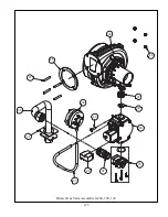
Страница 127: ...125 40 33 31 27 28 34 35 37 38 32 39 36 29 30 48 Blower Gas Valve Assembly for 80 100 120...
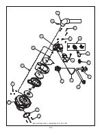
Страница 128: ...126 31 28 27 32 44 42 29 41 45 38 47 30 43 35 46 34 36 33 39 Blower Gas Valve Assembly for 150 180...
Страница 129: ...127...
Страница 131: ...129...
Страница 132: ...130...
Страница 133: ...131...
Страница 135: ...133...
Страница 137: ...135 140 141 142 143 144 145...

