UNITIZED TRANSAXLE
Component Assembly
2001 Pioneer 900 Gasoline Vehicle Maintenance and Service Manual Page 16-25
16
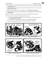
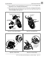
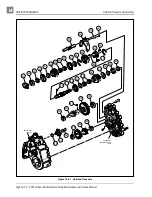
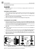
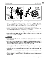
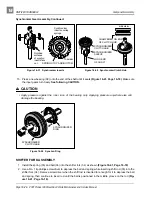
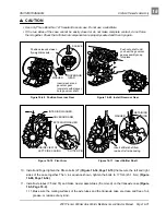
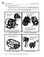
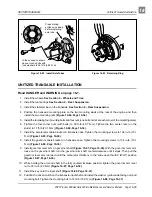
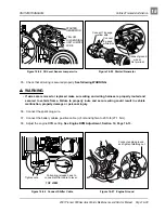
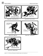
5. On the long end of the shaft, install the synchronizer ring (45) (Figure 16-41, Page 16-18) with the
smooth collar of the ring towards the clutch hub. Make sure the three notches in the collar mate with
the synchronizer inserts in the synchronizer sleeve as shown (Figure 16-59, Page 16-26).
6. Install the thrust washer (41) and two bearings (43) as shown (Figure 16-41, Page 16-18).
7. Install the input gear assembly (52), with the smooth collar toward the synchronizer ring as shown (Fig-
ure 16-41, Page 16-18). The input gear should seat in the synchronizer ring.
8. Install the thrust washer (53) and then the spring washer (39). The spring washer should be oriented
with the raised center toward the end of the shaft (Figure 16-41, Page 16-18).
9. Press new bearing (54) (Figure 16-41, Page 16-18) onto the shaft until it seats. Make sure the input
gear turns freely. See following CAUTION.
∆ CAUTION
• Apply pressure against the inner race of the bearing only. Applying pressure anywhere else will
damage the bearing.
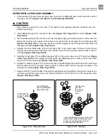
10. On the other end of the input shaft, install the thrust washer (41), and the synchronizer ring (45). The
smooth collar of the synchronizer ring should be oriented toward the clutch hub, and the notches in it
should mate with the synchronizer inserts as shown (Figure 16-41, Page 16-18).
11. Install the narrow bearing (44), wide bearing (43), and input gear (42) onto the shaft. The smooth collar
of the input gear should be oriented toward the synchronizer ring as shown (Figure 16-41, Page 16-
18). The gear should seat inside the ring.
12. Install thrust plate (41) onto the shaft, and the dowel pin (50) into the shaft as shown (Figure 16-41,
13. Install the spur (governor drive) gear (40) onto the shaft with either side down. Mate the notch in the
gear with the dowel pin as shown (Figure 16-41, Page 16-18).
14. Install the spring washer (39) onto shaft with the raised center toward the end of the shaft (Figure 16-
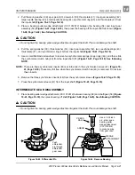
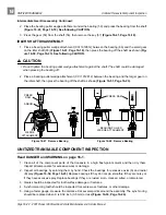
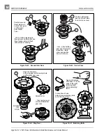
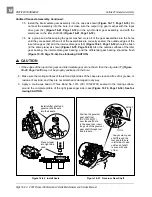
Figure 16-55 Synchro. Gear Assembly
Figure 16-56 Synchro. Springs
PRESS
RAM
SYNCHRONIZER
SLEEVE
INPUT
SHAFT
MACHINED
FACE OF
SYNCHRO.
SLEEVE
TOP OF SPLINE
Top of spline pressed
level with machined
face.
Install springs
on top and bottom
of synchronizer
sleeve as shown.
Ends
positioned
between
insert slots.
FRONT VIEW
SYNCHRONIZER
INSERT SLOTS
Содержание Pioneer 900
Страница 1: ......
Страница 2: ......
Страница 22: ...3...
Страница 88: ...7...
Страница 92: ...8...
Страница 100: ...9...
Страница 108: ...10...
Страница 188: ...12...
Страница 268: ...14...
Страница 272: ...15...
Страница 316: ...16...
Страница 332: ...17...
Страница 341: ......
Страница 342: ......
Страница 343: ......


