ELECTRICAL COMPONENTS
Lockout Cam Limit Switch
Page 12-18 2001 Pioneer 900 Gasoline Vehicle Maintenance and Service Manual
12
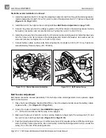
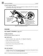
2. Install the snap-on electrical box cover by firmly pressing down on all corners and install the screw,
tightening to 18 in-lb (2 N·m).
3. Connect battery cables, positive cable first and tighten the terminals to 20 ft-lb (27.1 N·m). Coat termi-
nals with Battery Protector Spray (CCI 1014305).
LOCKOUT CAM LIMIT SWITCH
Read DANGER and WARNING on page 12-1.
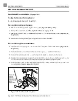
Testing the Lockout Cam Limit Switch
See Test Procedure 7, Section 11, Page 11-28.
Lockout Cam Limit Switch Removal
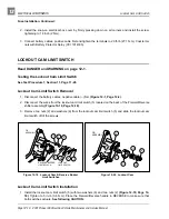
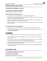
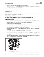
1. Disconnect the battery cables, negative cable (–) first (Figure 12-1, Page 12-2).
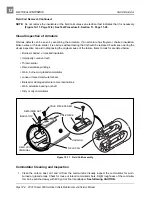
2. Disconnect the wires from the lockout cam limit switch (5) located on the back of the Forward/Reverse
shifter assembly (Figure 12-19, Page 12-18).
3. Remove two nuts (2) and washers (6) from the lockout cam limit switch (5) and slide the lockout cam
limit switch off of the screws.
Lockout Cam Limit Switch Installation
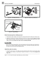
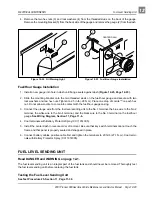
1. Install the lockout cam limit switch (5) with two washers (6) and two nuts (2) (Figure 12-19, Page 12-
18). Tighten to 5 in-lb (0.6 N·m). Place the Forward/Reverse handle in REVERSE to make sure that
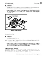
both switches actuate. See following CAUTION.
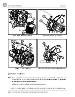
Figure 12-19 Lockout Cam & Reverse Buzzer
Limit Switches
Figure 12-20 Lockout Cam
COM
NC
NO
REVERSE BUZZER
LIMIT SWITCH
LOCKOUT
LIMIT SWITCH
2
4
9
5
6
2
3
F/R
ASSEMBLY
COM
NC
NO
11
12
5
13
14
F/R
ASSEMBLY
4
Содержание Pioneer 900
Страница 1: ......
Страница 2: ......
Страница 22: ...3...
Страница 88: ...7...
Страница 92: ...8...
Страница 100: ...9...
Страница 108: ...10...
Страница 188: ...12...
Страница 268: ...14...
Страница 272: ...15...
Страница 316: ...16...
Страница 332: ...17...
Страница 341: ......
Страница 342: ......
Страница 343: ......

