TROUBLESHOOTING AND ELECTRICAL SYSTEM
Test Procedures
2001 Pioneer 900 Gasoline Vehicle Maintenance and Service Manual Page 11-29
11
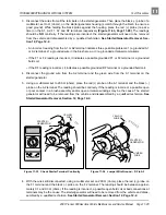
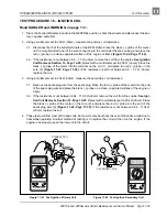
3. Disconnect the wires from all the terminals on the starter/generator. Then place the black (–) probe of a
multimeter, set to
Ω
(ohms), on the starter/generator housing (scratch through the finish to ensure a
good ground). While holding the black probe against the housing, place the red (+) probe (one at a
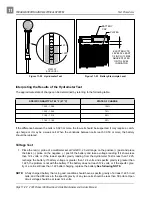
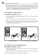
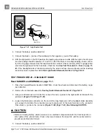
time) on the A1, A2, F1, F2 and DF terminals respectively (Figure 11-33, Page 11-29). The readings
should be NO continuity. If the readings are incorrect, the starter/generator will need to be removed
from the vehicle and disassembled by a qualified technician. See Starter/Generator Removal, Sec-
tion 12, Page 12-2.
- An incorrect reading from the A1 or A2 terminal indicates three possible problems: 1) a grounded A1
or A2 terminal, 2) a grounded wire in the brush area, or 3) a grounded armature/commutator.
- If the F1 or F2 reading is incorrect, it indicates a possible grounded F1 or F2 terminal or a grounded
field coil.
- If the DF reading is incorrect, it indicates a possible grounded DF terminal or a grounded field coil.
4. Disconnect the ground wire from the A2 terminal and the green wire from the A1 terminal on the
starter/generator.
5. Using a multimeter set to 200
Ω
(ohms), place the red (+) probe on the A1 terminal and the black (–)
probe on the A2 terminal. The reading should be continuity. If the reading is incorrect, a possible open
or poor contact in a brush assembly and/or open armature windings may be the cause. The starter/
generator will need to be removed from the vehicle and disassembled by a qualified technician. See
Starter/Generator Removal, Section 12, Page 12-2.
6. With the wires still disconnected, using a multimeter set on 200
Ω
(ohms), place the red (+) probe on
the F1 terminal and the black (–) probe on the F2 terminal. The reading should be between approxi-
mately 0.1 and 0.3
Ω
(ohms). If the reading is incorrect, a possible open field coil or bad connections at
terminals may be the cause. The starter/generator will need to be removed from the vehicle and disas-
sembled by a qualified technician. See Starter/Generator Removal, Section 12, Page 12-2.
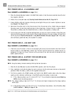
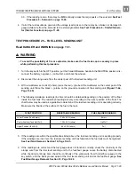
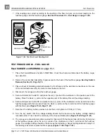
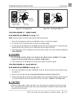
Figure 11-33 Check Starter Terminal Continuity
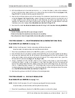
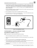
Figure 11-34 Jumper Wire Ground – DF to A2
2m
20
m
200
m
2k
200
200
200
200
20
2
200
m
500
20k
200k
2000
k
Ω
Ω
1000
OFF
WAVETEK
5XL
V
V
V
A
!
!
COM
200nA
MAX
1000 ---
750V
FUSED
F2
DF
F1
A2
A1
YELLOW
WIRE
STARTER /
GENERATOR
YELLOW
WIRE
JUMPER
WIRE
STARTER /
GENERATOR
F2
DF
F1
A2
A1
Содержание Pioneer 900
Страница 1: ......
Страница 2: ......
Страница 22: ...3...
Страница 88: ...7...
Страница 92: ...8...
Страница 100: ...9...
Страница 108: ...10...
Страница 188: ...12...
Страница 268: ...14...
Страница 272: ...15...
Страница 316: ...16...
Страница 332: ...17...
Страница 341: ......
Страница 342: ......
Страница 343: ......

