PANEL MODES
Each panel-mode area can operate
in six different modes, three of which
are commonly required. Users often
prefer to set three panels across the
console into each of these modes
to make the most commonly used
controls all visible at the same time.
The six panel modes available are:
•
PROCESSING
•
SEND-ROUTE
•
BUS & O/P (Outputs)
•
MON (Monitoring)
•
WILDS (Customer defined controls)
•
STRIPS (In-line controls)
•
OFF Each panel-mode area can also
be set to off if it is preferable not to
have more than one instance of each
mode on the surface.
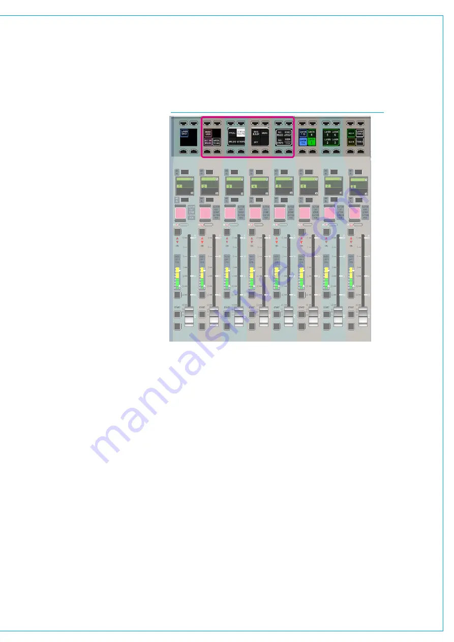
The mode of each panel area is selected
using the Modes Row controls highlighted
in Fig 1. The modes shown in the graphic
displays are selected by pressing the
button above or below. The currently
active mode is highlighted by the graphic
display and the button LED.
ModeToAll
Holding a panel mode select button down
then pressing MODE TO ALL will select
the chosen panel mode to all panels. This
is useful for example to quickly put the
whole control surface into Wilds mode.
ModeLock
Pressing the MODE LOCK button
removes the mode select buttons from
that panel and prevents it being changed
by an Apply All or the selection of a
console wide User Set. Pressing Mode
Lock again will unlock the mode.
Layouts
Layouts are stored arrangements of
modes on the surface panels. There are
four buttons Fixed Layout, User Layout,
All Wilds and All Strips. These buttons
are in the Modes & Layers button cell row
and allow switching between layouts. The
Fixed Layout will recall a pre-determined
layout of modes on each panel.
FIG 1 - PANEL MODE SELECTION BUTTONS
Settingup/RecallingtheUserLayout
To set up the User Layout, simply select
the modes for each panel on the console
in the arrangement that you wish them
to appear, then press and hold the USER
button. The text on the button briefly
displays SAVED to show that the process
has been successful. Press the USER
button to recall the saved panel mode
arrangements.
Fixedlayout
FIXED LAYOUT is a fixed arrangement of
modes on the surface panels included to
allow the user to return to a default layout.
Assignablemodes
The PROCESSING and SEND-ROUTE
panel modes are two of the most
commonly used modes. Both of these
are assignable control modes, in that they
display information for, and can adjust
parameters of the currently assigned audio
path. Unless user splits have been put into
place for multiple operators, only one audio
path is assigned at any given time.
The currently assigned path is shown
on the TFT screen in the upstand when
displaying in one of the two assignable
modes. If the currently assigned path
is on an active fader layer, it is also
highlighted by its fader label display and
assign button being illuminated blue. The
most common way to select an audio path
to make it the currently assigned path and
the focus of assignable panel modes is by
pressing the fader assign button directly
above (A layer) or below (B layer) a fader
label display.
The actual controls available in an
assignable panel mode may change
depending upon the type of audio path
which is currently assigned. For example,
mono and stereo paths have different pan
controls available to them. Paths with
analogue inputs patched to them have
phantom power buttons, whilst paths with
digital inputs have sample rate convertor
buttons. If a Main output is the currently
assigned path, fewer routing options are
available than if a channel or group path is
assigned.
CUT
CUT
CUT
CUT
CUT
CUT
CUT
CUT
AFL
PFL
DIR
TB
ISO
AFL
PFL
DIR
TB
ISO
AFL
PFL
DIR
TB
ISO
AFL
PFL
DIR
TB
ISO
AFL
PFL
DIR
TB
ISO
AFL
PFL
DIR
TB
ISO
AFL
PFL
DIR
TB
ISO
AFL
PFL
DIR
TB
ISO
Содержание Artemis
Страница 7: ...calrec com Putting Sound in the Picture ARTEMIS INFORMATION ...
Страница 11: ...calrec com Putting Sound in the Picture ARTEMIS INTRODUCTION ...
Страница 17: ...calrec com Putting Sound in the Picture ARTEMIS CONTROL OVERVIEW ...
Страница 29: ...calrec com Putting Sound in the Picture ARTEMIS CONTROL PANEL MODES ...
Страница 36: ...36 ARTEMIS Digital Broadcast Production Console Control Panel Modes WILDABLE CONTROLS ...
Страница 39: ...calrec com Putting Sound in the Picture ARTEMIS GETTING SIGNALS INTO ARTEMIS ...
Страница 69: ...calrec com Putting Sound in the Picture ARTEMIS PROCESSING AUDIO ...
Страница 93: ...calrec com Putting Sound in the Picture ARTEMIS ROUTING AUDIO ...
Страница 109: ...calrec com Putting Sound in the Picture ARTEMIS PASSING SIGNALS OUT OF ARTEMIS ...
Страница 117: ...calrec com Putting Sound in the Picture ARTEMIS MONITORING ...
Страница 132: ...132 ARTEMIS Digital Broadcast Production Console Monitoring ...
Страница 133: ...calrec com Putting Sound in the Picture ARTEMIS COMMUNICATIONS ...
Страница 138: ...138 ARTEMIS Digital Broadcast Production Console ...
Страница 139: ...calrec com Putting Sound in the Picture ARTEMIS METERING ...
Страница 148: ...148 ARTEMIS Digital Broadcast Production Console ...
Страница 149: ...calrec com Putting Sound in the Picture ARTEMIS SHOWS MEMORIES AND PRESETS ...
Страница 163: ...calrec com Putting Sound in the Picture ARTEMIS CONSOLE FACILITIES ...
Страница 168: ...168 ARTEMIS Digital Broadcast Production Console ...
Страница 169: ...calrec com Putting Sound in the Picture ARTEMIS EXTERNAL INTERFACING ...
Страница 180: ...180 ARTEMIS Digital Broadcast Production Console External Interfacing ...
Страница 181: ...calrec com Putting Sound in the Picture ARTEMIS SYSTEM STATUS ...
Страница 184: ...184 ARTEMIS Digital Broadcast Production Console ...
Страница 185: ...calrec com Putting Sound in the Picture ARTEMIS GLOSSARY OF TERMINOLOGY ...
Страница 191: ...calrec com Putting Sound in the Picture ARTEMIS FEATURES BY SOFTWARE VERSION ...


