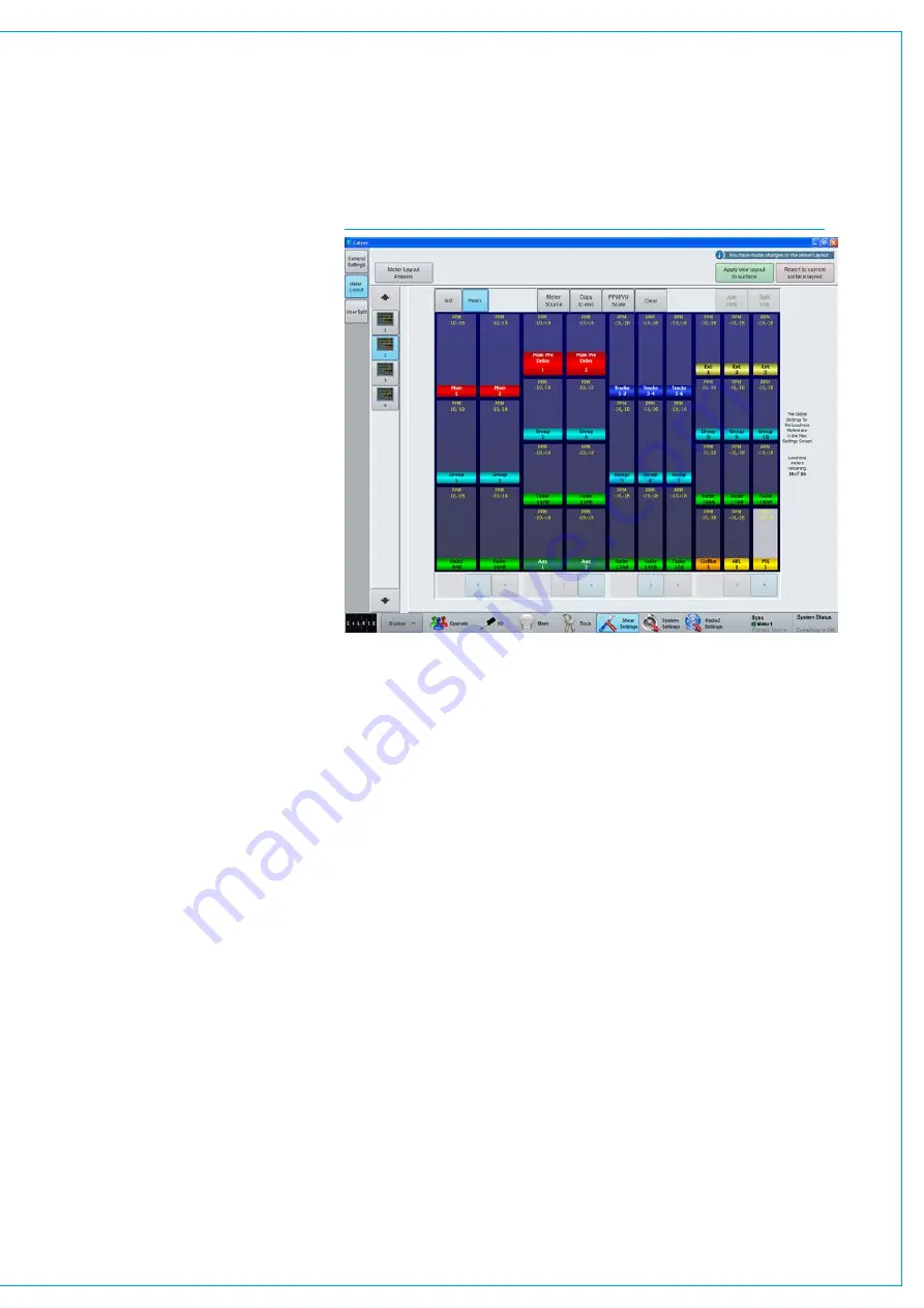
The buttons at the base of each vertical
section set the vertical cell division e.g
selecting 3, splits the TFT so that there
are 3 cells within the vertical space.
Individual cells can be selected to have
2 or 3 cells horizontally using the number
selection buttons within each cell.
Larger vertical heights can then be
created by joining cells. To create meters
higher than a third or quarter of the screen
first select the ‘Meters’ tab. Adjacent
vertical areas of the same width can
then be joined by touching the upper of
the two cells to be linked, then touching
‘Join cells’.
Combining
⅓
and
¼
height meters with
2 and 3 wide cells allows a vast range of
alternative grids. To reduce the vertical
meter height that are bigger than one cell
select it and touch ‘Split cell’.
As soon as changes are entered, the
message
‘You have made changes to
the meter layout
’ appears and the user
can then Click the ‘Apply new layout to
surface’ button in the top right corner to
apply the meter settings on the screen to
the control surface, or ‘Revert to current
surface layout’ to put it back as it was.
MeterAssignment
Once the grid of meter cells has been
defined, meters can be inserted into each
cell. Select ‘Meters’ at the top of the
window, then either click on a meter cell
and then click ‘Meter Source’ at the top
of the window, or press and hold/double
click on the meter cell, see Fig 4.
These two methods both bring up the
meter source selection pop-up window.
Within the pop-up, selecting a source
type from the buttons down the left hand
side populates the main window with all
available meter source options of that
type.
Some meter sources have sub options,
such as choosing a loudness meter, or an
A/B fader path meter.
Once you have selected a meter source
touch ‘Apply to selected’ to add that meter
source and function to the selected meter
cell.
Alternatively, ‘Apply to end of row’ sets
the selected cell to the assigned meter
function and each cell to the right to the
same type with an increment of one. For
example, if the first meter was assigned to
meter Track 1, the next would meter Track
2 etc. This is only the case when there
are similarly sized unassigned meter cells
to the right of the selected cell, and the
meter function is part of a sequence of
similar sources. If there are already some
meters assigned in the row and you wish
to incrementally overwrite these meters,
click ‘Overwrite to end of row’.
MeterScales
Each meter can be set either PPM or
VU mode. PPM characteristics are fast
attack and slow decay to show audible
peaks. VU characteristics are slow
attack and fast decay to show average
level. There are four PPM scales, -8...-20,
-9...-15, -10...-18 and -12...-18. and there
are three VU scales are -8...-20, -12...-20
and -20. Scale settings can be copied
to adjacent similarly sized meter cells by
choosing ‘Apply to end’.
Meterlabelsandcolours
The colour bar beneath each meter
relates to the colouring of paths used
throughout the surface. Red corresponds
to main paths, dark blue to tracks, green
to auxs, light blue to groups and so on.
A and B path colours correspond to the
A and B path selector buttons above
the faders which are green and yellow
respectively. Note that the current assign
meter is also now highlighted in Blue.
FIG 4 - METER ASSIGNMENT
Содержание Artemis
Страница 7: ...calrec com Putting Sound in the Picture ARTEMIS INFORMATION ...
Страница 11: ...calrec com Putting Sound in the Picture ARTEMIS INTRODUCTION ...
Страница 17: ...calrec com Putting Sound in the Picture ARTEMIS CONTROL OVERVIEW ...
Страница 29: ...calrec com Putting Sound in the Picture ARTEMIS CONTROL PANEL MODES ...
Страница 36: ...36 ARTEMIS Digital Broadcast Production Console Control Panel Modes WILDABLE CONTROLS ...
Страница 39: ...calrec com Putting Sound in the Picture ARTEMIS GETTING SIGNALS INTO ARTEMIS ...
Страница 69: ...calrec com Putting Sound in the Picture ARTEMIS PROCESSING AUDIO ...
Страница 93: ...calrec com Putting Sound in the Picture ARTEMIS ROUTING AUDIO ...
Страница 109: ...calrec com Putting Sound in the Picture ARTEMIS PASSING SIGNALS OUT OF ARTEMIS ...
Страница 117: ...calrec com Putting Sound in the Picture ARTEMIS MONITORING ...
Страница 132: ...132 ARTEMIS Digital Broadcast Production Console Monitoring ...
Страница 133: ...calrec com Putting Sound in the Picture ARTEMIS COMMUNICATIONS ...
Страница 138: ...138 ARTEMIS Digital Broadcast Production Console ...
Страница 139: ...calrec com Putting Sound in the Picture ARTEMIS METERING ...
Страница 148: ...148 ARTEMIS Digital Broadcast Production Console ...
Страница 149: ...calrec com Putting Sound in the Picture ARTEMIS SHOWS MEMORIES AND PRESETS ...
Страница 163: ...calrec com Putting Sound in the Picture ARTEMIS CONSOLE FACILITIES ...
Страница 168: ...168 ARTEMIS Digital Broadcast Production Console ...
Страница 169: ...calrec com Putting Sound in the Picture ARTEMIS EXTERNAL INTERFACING ...
Страница 180: ...180 ARTEMIS Digital Broadcast Production Console External Interfacing ...
Страница 181: ...calrec com Putting Sound in the Picture ARTEMIS SYSTEM STATUS ...
Страница 184: ...184 ARTEMIS Digital Broadcast Production Console ...
Страница 185: ...calrec com Putting Sound in the Picture ARTEMIS GLOSSARY OF TERMINOLOGY ...
Страница 191: ...calrec com Putting Sound in the Picture ARTEMIS FEATURES BY SOFTWARE VERSION ...


