Digital Broadcast Production Console
Moving/SwappingPaths
Two paths that are attached to faders
on the surface can have their locations
swapped. All settings on the paths
remain intact, this function simply swaps
the faders that control two paths.
To swap the location of two paths:
1. In a similar way to cloning a path, push
the ASSIGN button of one of the paths
to be swapped.
2. Push the LAYER TOOLS button to
update the row above.
3. Push and hold the SWAP PATH button
on the functions row then press the
assign button of the other path which is
to be swapped. The assign buttons of
the two paths should now be flashing
to indicate the selection.
4. Release the SWAP PATH button and
press the EXEC button to confirm the
process or press the CNCL button to
cancel the process and leave the path
positions unchanged.
The path on the first fader moves to the
second fader selected, and at the same
time the path on the second fader moves
to the first rather than being removed.
Faders with no path allocated can also
be selected as part of the swap-path
process, i.e a path can be moved to a
blank fader, leaving its original fader blank.
Swapping paths moves the whole DSP
signal path from one physical fader to
another. The input source and its settings
along with DSP and routing settings are
all moved from one fader to another.
Cloningpaths
Input channels can be allocated to
multiple faders to allow control from
different physical locations or fader layers.
By cloning a path, the same DSP signal
path is being accessed and controlled
from more than one physical fader.
Adjustments made from any of them are
reflected on the others. This is similar in
concept to assigning the same group or
Main bus to more than one fader.
Select the assign button of the path to
be cloned. Press and hold the CLONE
FADER button from the LAYER TOOLS
menu and then select the assign button
of an unallocated fader that the clone is
to be placed on. Press EXEC to execute
or CNCL to cancel the operation. Faders
for cloned channel paths indicate a clone
icon in their label display to differentiate
between clones of paths and separate
channel paths that have the same input
source patched. See Fig 8 below.
Cloning Main or group paths in this way
is exactly the same as assigning the
same bus to multiple faders from the
TOOLS>FADER ASSIGNMENT menu.
Instances of the same group or Main bus
on more than one fader are always clones
and as such do not require a clone icon in
their display to differentiate.
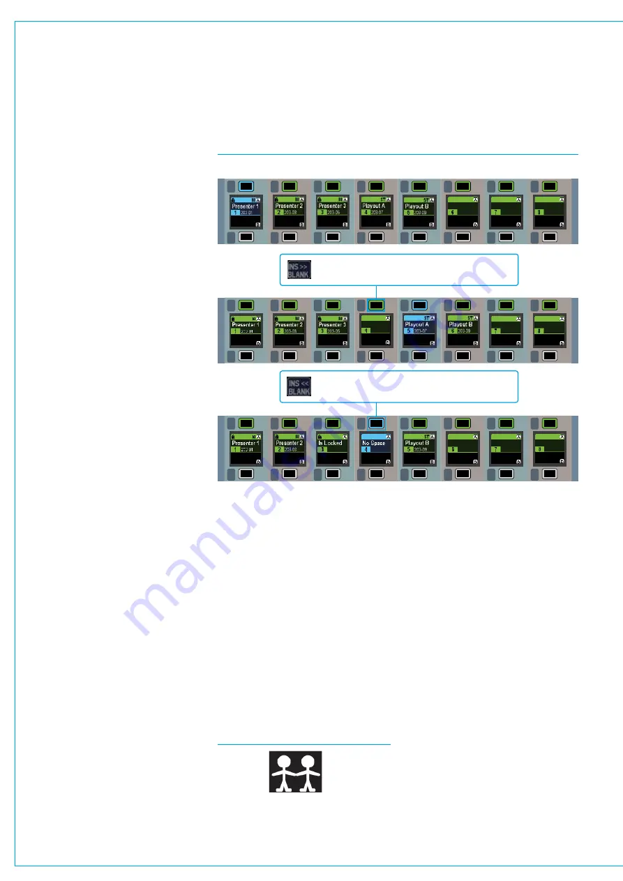
Insertingblankfaders
Paths can be shuffled left or right on
the control surface in order to make an
unallocated fader available in the middle
of a group of allocated faders.
From the TOOLS>FADER ASSIGNMENT
menu, press and hold INS << BLANK or
INS >> BLANK and then press the A or B
assign button of the fader where the blank
is to be inserted. See Fig 7 above.
A blank may only be inserted if there is a
free fader to allow the consecutive paths
to the left or right to be shuffled down
the control surface. If no blank fader is
available, the existing paths cannot shuffle
and the blank will not be inserted.
FIG 7 - INSERTING BLANKS
MR
SL
MR
SL
MR
SL
MR
SL
MR
SL
MR
SL
MR
SL
MR
SL
MR
SL
MR
SL
MR
SL
MR
SL
MR
SL
MR
SL
MR
SL
MR
SL
MR
SL
MR
SL
MR
SL
MR
SL
MR
SL
MR
SL
MR
SL
MR
SL
MR
SL
MR
SL
MR
SL
MR
SL
MR
SL
MR
SL
MR
SL
MR
SL
MR
SL
MR
SL
MR
SL
MR
SL
MR
SL
MR
SL
MR
SL
MR
SL
MR
SL
MR
SL
MR
SL
MR
SL
MR
SL
MR
SL
MR
SL
MR
SL
Inserting a blank and shuffling existing faders to the right is
allowed here. There is nothing to block the path of the
shuffled faders.
The arrangement of paths below serves as the starting point for the two following examples.
Inserting a blank and shuffling existing faders to the left is
NOT allowed here. Locked faders are blocking the path of
the faders to be shuffled.
FIG 8 - CLONED FADER ICON
Содержание Artemis
Страница 7: ...calrec com Putting Sound in the Picture ARTEMIS INFORMATION ...
Страница 11: ...calrec com Putting Sound in the Picture ARTEMIS INTRODUCTION ...
Страница 17: ...calrec com Putting Sound in the Picture ARTEMIS CONTROL OVERVIEW ...
Страница 29: ...calrec com Putting Sound in the Picture ARTEMIS CONTROL PANEL MODES ...
Страница 36: ...36 ARTEMIS Digital Broadcast Production Console Control Panel Modes WILDABLE CONTROLS ...
Страница 39: ...calrec com Putting Sound in the Picture ARTEMIS GETTING SIGNALS INTO ARTEMIS ...
Страница 69: ...calrec com Putting Sound in the Picture ARTEMIS PROCESSING AUDIO ...
Страница 93: ...calrec com Putting Sound in the Picture ARTEMIS ROUTING AUDIO ...
Страница 109: ...calrec com Putting Sound in the Picture ARTEMIS PASSING SIGNALS OUT OF ARTEMIS ...
Страница 117: ...calrec com Putting Sound in the Picture ARTEMIS MONITORING ...
Страница 132: ...132 ARTEMIS Digital Broadcast Production Console Monitoring ...
Страница 133: ...calrec com Putting Sound in the Picture ARTEMIS COMMUNICATIONS ...
Страница 138: ...138 ARTEMIS Digital Broadcast Production Console ...
Страница 139: ...calrec com Putting Sound in the Picture ARTEMIS METERING ...
Страница 148: ...148 ARTEMIS Digital Broadcast Production Console ...
Страница 149: ...calrec com Putting Sound in the Picture ARTEMIS SHOWS MEMORIES AND PRESETS ...
Страница 163: ...calrec com Putting Sound in the Picture ARTEMIS CONSOLE FACILITIES ...
Страница 168: ...168 ARTEMIS Digital Broadcast Production Console ...
Страница 169: ...calrec com Putting Sound in the Picture ARTEMIS EXTERNAL INTERFACING ...
Страница 180: ...180 ARTEMIS Digital Broadcast Production Console External Interfacing ...
Страница 181: ...calrec com Putting Sound in the Picture ARTEMIS SYSTEM STATUS ...
Страница 184: ...184 ARTEMIS Digital Broadcast Production Console ...
Страница 185: ...calrec com Putting Sound in the Picture ARTEMIS GLOSSARY OF TERMINOLOGY ...
Страница 191: ...calrec com Putting Sound in the Picture ARTEMIS FEATURES BY SOFTWARE VERSION ...


