INPUT TYPES AND PATCHING
The main application
>I/O>I/O Patch
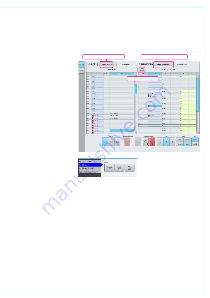
screen is used to route Hydra2 audio
input & output ports for general use.
This screen works on a source to
destination basis, with the left hand side of
the screen displaying a table of sources,
and the right hand side displaying a table
of destinations. See Fig 1. All patches
made from the I/O screen are saved as
part of the user memory.
Portsatdifferentsamplerates
Note that now different sample rates are
available, ports set to a different sample
rate to that of the show appear with the
SR kHz warning icon to indicate that it
cannot be used unless the sample rate of
it’s associated I/O box is changed in H2O
or a different show is loaded using the
correct sample rate. See Fig 1.
Searchinginputsources
The source and destination lists are
filtered by type. Click on the Select
Source button at the top of the sources
list to bring up the Available Sources
menu. See Fig 2. Source types are
shown in a column on the left side of this
menu, highlighting ‘Input Ports’ displays
a series of buttons for the Hydra2 input
port lists, as defined by the
>Hydra2
Settings>Port Lists & Labels
screen (see
the Input Source Organization section for
more details on port lists). The Default
List contains all Hydra2 input ports that
have been made available. If port lists
have not been customised, there will be
a separate list for each Hydra2 I/O box,
labelled with the box ID numbers. Custom
lists may have been created and/or
individual box by ID lists deleted. Custom
lists are commonly used to group ports
by location or type, for example ‘Studio 1
Mic’s’, ‘VT machines’ etc. Selecting a port
list closes the Available Sources Menu
and displays the list in the sources table.
Searchingdestinations
Click on the ‘Select Destination’ button
at the top of the destinations table to
bring up the Available Destinations menu.
Destination types are listed in a column
down the right hand side of this menu.
Highlighting ‘My Desk Inputs’ displays the
types of DSP inputs available to patch
to, clicking ‘Channel I/Ps’ closes the
Available Destinations menu and displays
a table of the control surface faders.
Channelinput/faderviews
When displaying channel inputs, the right
hand column of the destinations table, and
the text field above the table show the
fader layer being viewed. Different fader
layers can be viewed by clicking Select
Layer. Choosing ‘Desk Layer’ makes the
screen follow whichever is the active layer
on the control surface.
Note that each channel path has two
inputs which it can switch between,
allowing the source on a channel fader to
be quickly changed without re-patching.
Channelinput2
Input 2 is often used for backup sources
such as secondary microphones. The
input 1/2 switch takes place at the front
of the DSP channel path - all processing,
such as EQ, dynamics and routing of
the channel is the same irrespective
of whether input 1 or input 2 is active,
meaning that changing to a backup
source in this way not only utilises
the same fader but also ensures all
processing and routing is the same as
when using the original source.
The two inputs do have independent
controls for input specific functions, such
as analogue gain and phantom power,
allowing for different types of sources to
be used on the two inputs.
As well as fader layer, the text field above
the destinations table also shows whether
it is displaying input 1 or input 2. Buttons
in the right hand corner beneath the table
are used to switch between displaying
Input 1 & Input 2. The labels are
highlighted when viewing input 2 to draw
attention to the fact that these are not the
default inputs.
This screen is used for the patching
and viewing of patches only, the actual
switching of a channel between using
input 1 and input 2 is performed from the
PROCESSING panel mode.
FIG 1 - MAIN APPLICATION, I/O>I/O PATCH SCREEN SHOWING DESK INPUTS
FIG 2 - AVAILABLE SOURCES POP-UP
Change source list / type
Change destination list / type
Change fader layer
Содержание Artemis
Страница 7: ...calrec com Putting Sound in the Picture ARTEMIS INFORMATION ...
Страница 11: ...calrec com Putting Sound in the Picture ARTEMIS INTRODUCTION ...
Страница 17: ...calrec com Putting Sound in the Picture ARTEMIS CONTROL OVERVIEW ...
Страница 29: ...calrec com Putting Sound in the Picture ARTEMIS CONTROL PANEL MODES ...
Страница 36: ...36 ARTEMIS Digital Broadcast Production Console Control Panel Modes WILDABLE CONTROLS ...
Страница 39: ...calrec com Putting Sound in the Picture ARTEMIS GETTING SIGNALS INTO ARTEMIS ...
Страница 69: ...calrec com Putting Sound in the Picture ARTEMIS PROCESSING AUDIO ...
Страница 93: ...calrec com Putting Sound in the Picture ARTEMIS ROUTING AUDIO ...
Страница 109: ...calrec com Putting Sound in the Picture ARTEMIS PASSING SIGNALS OUT OF ARTEMIS ...
Страница 117: ...calrec com Putting Sound in the Picture ARTEMIS MONITORING ...
Страница 132: ...132 ARTEMIS Digital Broadcast Production Console Monitoring ...
Страница 133: ...calrec com Putting Sound in the Picture ARTEMIS COMMUNICATIONS ...
Страница 138: ...138 ARTEMIS Digital Broadcast Production Console ...
Страница 139: ...calrec com Putting Sound in the Picture ARTEMIS METERING ...
Страница 148: ...148 ARTEMIS Digital Broadcast Production Console ...
Страница 149: ...calrec com Putting Sound in the Picture ARTEMIS SHOWS MEMORIES AND PRESETS ...
Страница 163: ...calrec com Putting Sound in the Picture ARTEMIS CONSOLE FACILITIES ...
Страница 168: ...168 ARTEMIS Digital Broadcast Production Console ...
Страница 169: ...calrec com Putting Sound in the Picture ARTEMIS EXTERNAL INTERFACING ...
Страница 180: ...180 ARTEMIS Digital Broadcast Production Console External Interfacing ...
Страница 181: ...calrec com Putting Sound in the Picture ARTEMIS SYSTEM STATUS ...
Страница 184: ...184 ARTEMIS Digital Broadcast Production Console ...
Страница 185: ...calrec com Putting Sound in the Picture ARTEMIS GLOSSARY OF TERMINOLOGY ...
Страница 191: ...calrec com Putting Sound in the Picture ARTEMIS FEATURES BY SOFTWARE VERSION ...


