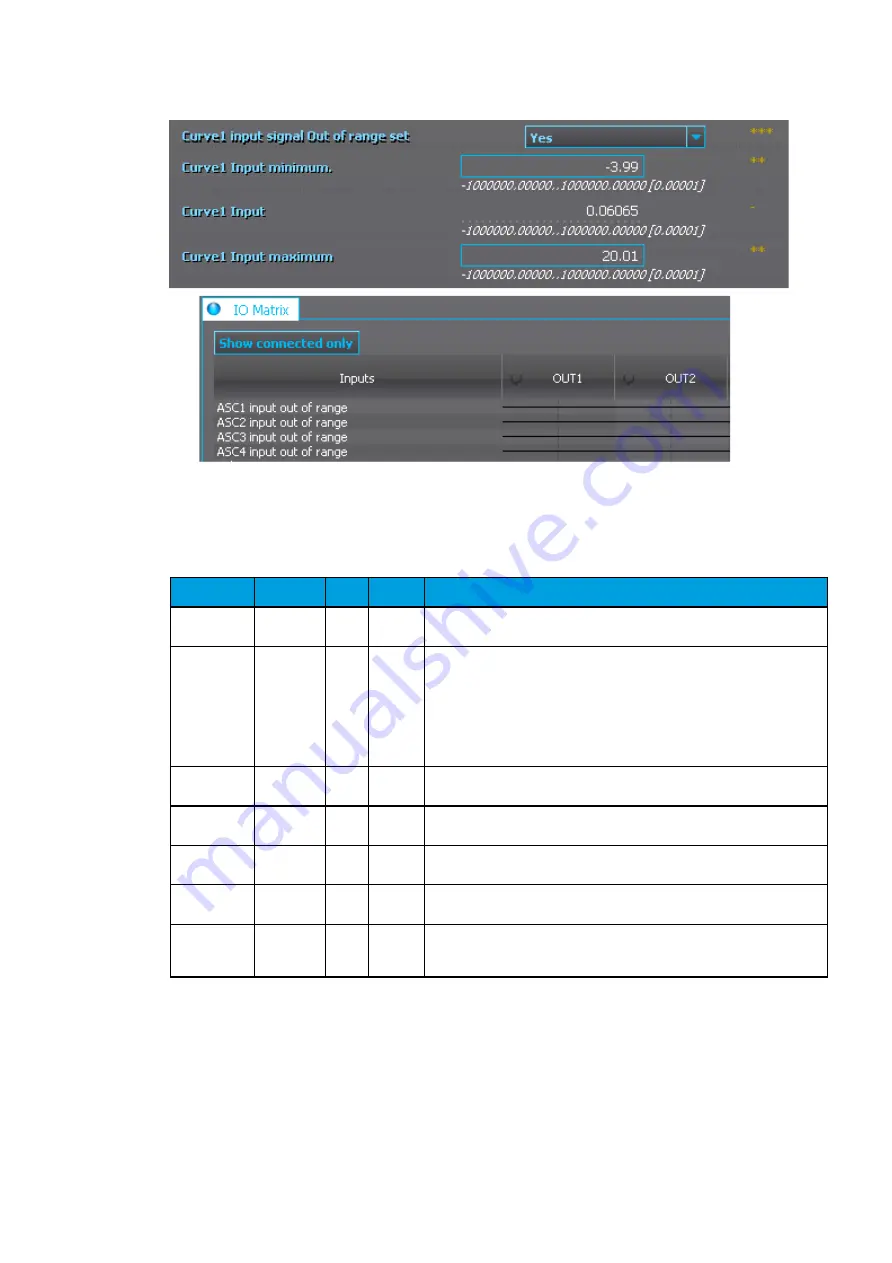
If for some reason the mA input signal is lost, the value is xed to the last actual measured cycle value.
The value does not go down to the minimum if it has been something else at the time of the signal
breaking.
Table. 5.5.4. - 97. Output settings and indications.
Name
Range
Step Default
Description
Curve 1...4
update cycle
5...10 000
ms
5 ms
150 ms
De nes the length of the mA input measurement update cycle. If the user
wants a fast operation, this setting should be fairly low.
Scaled value
handling
0: Floating
point
1: Integer
out (Floor)
2: Integer
(Ceiling)
3: Integer
(Nearest)
-
0:
Floating
point
Rounds the milliampere signal output as selected.
Input value 1
0...4000
0.000
01
0
The measured milliampere input value at Curve Point 1.
Scaled output
value 1
-10
7
...10
7
0.000
01
0
Scales the measured milliampere signal at Point 1.
Input value 2
0...4000
0.000
01
1
The measured milliampere input value at Curve Point 2.
Scaled output
value 1
-10
7
...10
7
0.000
01
0
Scales the measured milliampere signal at Point 2.
Add
curvepoint
3...20
0: Not
used
1: Used
-
0: Not
used
Allows the user to create their own curve with up to twenty (20) curve
points, instead of using a linear curve between two points.
5.5.5. Programmable control switch
The programmable control switch is a control function that controls its binary output signal. This output
signal can be controlled locally from the relay's mimic (displayed as a box in the mimic) or remotely
from the RTU. The main purpose of programmable control switches is to block or enable function and
to change function properties by changing the setting group. However, this binary signal can also be
used for any number of other purposes, just like all other binary signals. Once a programmable control
switch has been activated or disabled, it remains in that state until given a new command to switch to
the opposite state (see the image below). The switch cannot be controlled by an auxiliary input, such
as digital inputs or logic signals; it can only be controlled locally (mimic) or remotely (RTU).
AQ-E215
Instruction manual
Version: 2.01
© Arcteq Relays Ltd
118
Содержание AQ-E215
Страница 1: ...AQ E215 Energy management IED Instruction manual ...
Страница 4: ...206 11 Contact and reference information AQ E215 Instruction manual Version 2 01 3 Arcteq Relays Ltd ...
Страница 186: ...Figure 8 13 113 Device installation AQ E215 Instruction manual Version 2 01 185 Arcteq Relays Ltd ...
Страница 206: ... Pt100 1000 Balco500 Ni power module AQ E215 Instruction manual Version 2 01 205 Arcteq Relays Ltd ...


