


106
ACS550 User’s Manual
Start-Up
3013
UNDERLOAD FUNCTION
Removal of motor load may indicate a process malfunction. The protection is activated if:
• The motor torque drops below the load curve selected by parameter 3015
UNDERLOAD
CURVE
.
• This condition has lasted longer than the time set by parameter 3014
UNDERLOAD
TIME
.
• Output frequency is higher than 10% of the nominal frequency.
0 =
NOT
SEL
– Underload protection is not used.
1 =
FAULT
– When the protection is activated the drive coasts to stop. A fault indication is displayed.
2 =
WARNING
– A warning indication is displayed.
3014
UNDERLOAD TIME
Time limit for underload protection.
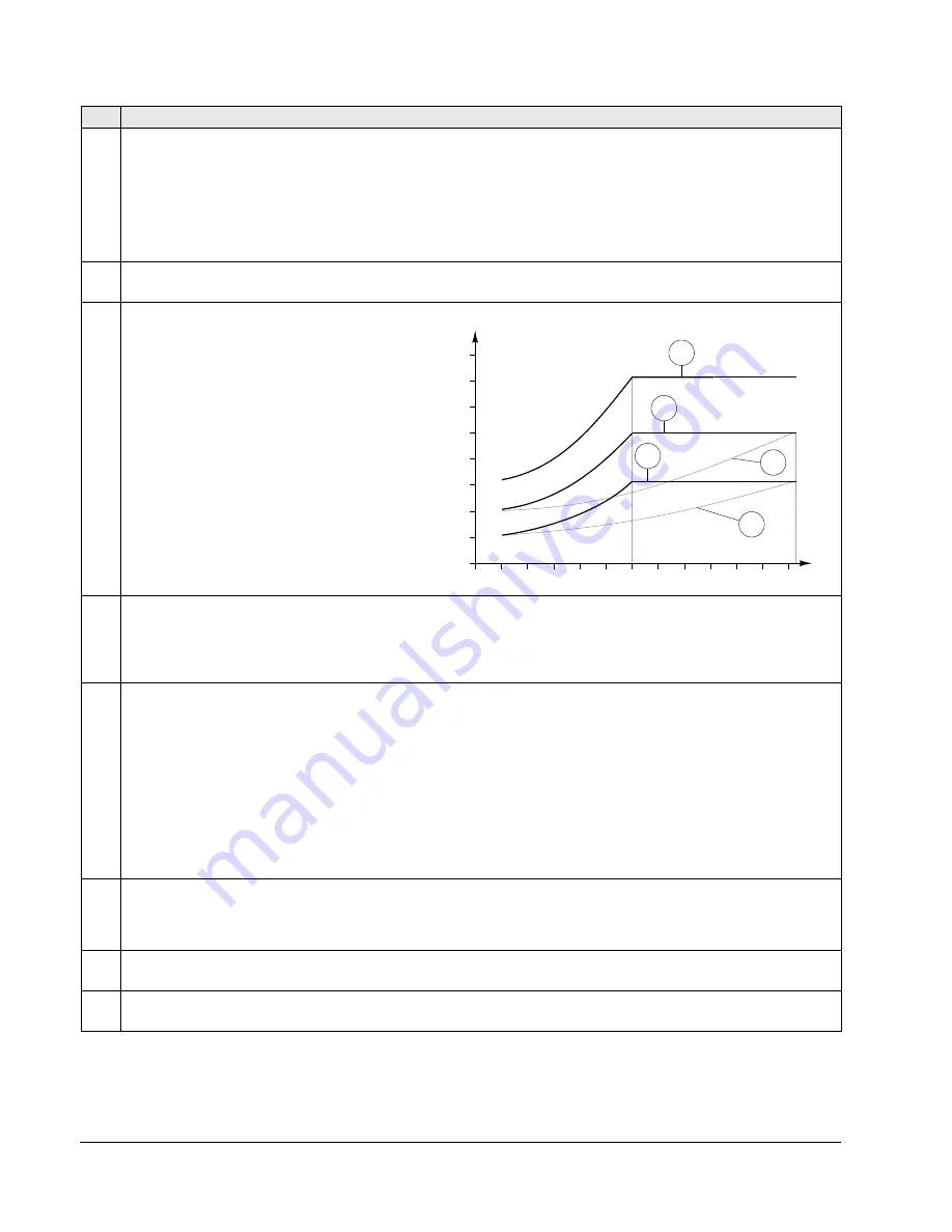
3015
UNDERLOAD CURVE
This parameter provides five selectable curves
shown in the figure.
• If the load drops below the set curve for longer
than the time set by parameter 3014, the
underload protection is activated.
• Curves 1…3 reach maximum at the motor rated
frequency set by parameter 9907
MOTOR
NOM
FREQ
.
• T
M
= nominal torque of the motor.
• ƒ
N
= nominal frequency of the motor.
3017
EARTH FAULT
Defines the drive response if the drive detects a ground fault in the motor or motor cables. The drive monitors for
ground faults while the drive is running, and while the drive is not running. Also see parameter 3023
WIRING
FAULT
.
0 =
DISABLE
– No drive response to ground faults.
1 =
ENABLE
– Ground faults display fault 16 (
EARTH
FAULT
), and (if running) the drive coasts to stop.
3018
COMM FAULT FUNC
Defines the drive response if the fieldbus communication is lost.
0 =
NOT
SEL
– No response.
1 =
FAULT
– Displays a fault (28,
SERIAL
1
ERR
) and the drive coasts to stop.
2 =
CONST
SP
7 – Displays a warning (2005,
I
/
O
COMM
) and sets speed using 1208
CONST
SPEED
7. This “alarm speed”
remains active until the fieldbus writes a new reference value.
3 =
LAST
SPEED
– Displays a warning (2005,
I
/
O
COMM
) and sets speed using the last operating level. This value is the
average speed over the last 10 seconds. This “alarm speed” remains active until the fieldbus writes a new
reference value.
Caution
: If you select
CONST
SP
7, or
LAST
SPEED
, make sure that continued operation is safe when fieldbus
communication is lost.
3019
COMM FAULT TIME
Sets the communication fault time used with 3018
COMM
FAULT
FUNC
.
• Brief interruptions in the fieldbus communication are not treated as faults if they are less than the
COMM
FAULT
TIME
value.
3021
AI1 FAULT LIMIT
Sets a fault level for analog input 1. See 3001
AI
<
MIN
FUNCTION
.
3022
AI2 FAULT LIMIT
Sets a fault level for analog input 2. See 3001
AI
<
MIN
FUNCTION
.
Code Description
80
60
40
20
0
2.4 * ƒ
N
3
2
1
5
4
T
M
70%
50%
30%
ƒ
N
(%)
Underload curve types
f


