Diagnostic & Troubleshooting 6 - 8
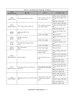
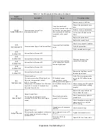
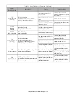
CPF04
Internal A/D Err
CPU Internal A/D Converter Fault
Noise or spike on the control
circuit input terminals.
Perform a factory initialization.
Cycle power off and on to the
Drive.
Replace the control board.
CPF05
External A/D Err
CPU External A/D Converter Fault
Noise or spike on the control
circuit input terminals.
Perform a factory initialization.
Cycle power off and on to the
Drive.
Replace the control board.
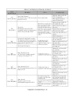
CPF07
RAM-Err
ASIC Internal RAM Fault
(RAM)
- - -
Cycle power off and on to the
Drive.
Control circuit damage
Replace the Drive.
CPF08
WAT-Err
Watchdog Timer Fault
(WAT)
- - -
Cycle power off and on to the
Drive.
Control circuit damage
Replace the Drive.
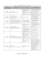
CPF09
CPU-Err
CPU-ASIC Mutual Diagnosis Fault
(COY)
- - -
Cycle power off and on to the
Drive.
Control circuit damage
Replace the Drive.
CPF10
ASIC-Err
ASIC Version Fault
(ASIC)
Control circuit damage
Replace the Drive.
CPF20
Option A/D Error
Option Card Fault
Option card connector
connection fault.
Remove all inputs to the option
board.
Option card A/D converter
fault.
Perform a factory initialization.
Cycle power off and on to the
Drive.
Replace the option board.
Replace the Control board.
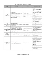
CPF21
Option CPU Down
Self-diagnosis Fault of Communication
Option Card
Noise or spike on the commu-
nication line, defective option
board.
Perform a factory initialization.
Cycle power off and on to the
Drive.
Replace the option board.
Replace the control board.
CPF22
Option Type Err
Communication Option Card Code Number
Fault
Unrecognizable option board
is connected to the control
board.
Remove any option boards.
Cycle power off and on to the
Drive.
Perform a factory initialization.
Replace the option board.
Replace the control board.
Table 6.3 Fault Displays and Processing (Continued)
Digital
Operator Display
Description
Cause
Corrective Action
Summary of Contents for E7LBA002
Page 1: ...E7L Drive Bypass Technical Manual Model E7L Document Number TM E7L 01 ...
Page 8: ...Introduction vi Notes ...
Page 12: ...Table of Contents x Notes ...
Page 54: ...Electrical Installation 2 22 Wiring Diagram ...
Page 55: ...Electrical Installation 2 23 ...
Page 87: ...Start Up and Operation 4 9 Notes ...
Page 202: ...Diagnostic Troubleshooting 6 30 Notes ...
Page 248: ...Capacity Related Parameters B 6 Notes ...
Page 279: ...Communications D 27 Note ...
Page 280: ...Communications D 28 ...
Page 292: ...Spare Parts F 6 ...
Page 304: ...Index 12 ...
Page 305: ......

