


Diagnostic & Troubleshooting 6 - 27
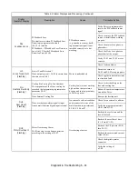
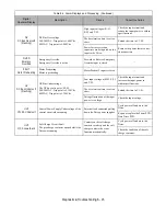
Table 6.8 Main Circuit Test Procedure (Continued)
Check
Procedure
Output Transistors
(Q1-Q12)
The output transistors are used to switch the DC bus voltage to allow current to flow to the
motor.
1. Set a digital multi-meter to the Diode Check setting.
2
Place the positive (red) meter lead on terminal U/T1.
Place the negative (black) meter lead on terminal
⊕
1.
Expected reading is about 0.5 Volts.
3
Place the positive (red) meter lead on terminal V/T2.
Place the negative (black) meter lead on terminal
⊕
1.
Expected reading is about 0.5 Volts.
4
Place the positive (red) meter lead on terminal W/T3.
Place the negative (black) meter lead on terminal
⊕
1.
Expected reading is about 0.5 Volts.
5
Place the positive (red) meter lead on terminal U/T1.
Place the negative (black) meter lead on terminal (-).
Expected reading is OL displayed.
6. Place the positive (red) meter lead on terminal V/T2.
Place the negative (black) meter lead on terminal (-).
Expected reading is OL displayed.
7
Place the positive (red) meter lead on terminal W/T3.
Place the negative (black) meter lead on terminal (-).
Expected reading is OL displayed.
8
Place the positive (red) meter lead on terminal (-).
Place the negative (black) meter lead on terminal U/T1.
Expected reading is about 0.5 Volts.
9
Place the positive (red) meter lead on terminal (-).
Place the negative (black) meter lead on terminal V/T2.
Expected reading is about 0.5 Volts.
10 Place the positive (red) meter lead on terminal (-).
Place the negative (black) meter lead on terminal W/T3.
Expected reading is about 0.5 Volts.
11. Place the positive (red) meter lead on terminal
⊕
1.
Place the negative (black) meter lead on terminal U/T1.
Expected reading is OL displayed.
12. Place the positive (red) meter lead on terminal
⊕
1.
Place the negative (black) meter lead on terminal V/T2.
Expected reading is OL displayed.
13. Place the positive (red) meter lead on terminal
⊕
1.
Place the negative (black) meter lead on terminal W/T3.
Expected reading is OL displayed.
Control Power Fuse
All Drives have a Control Power Fuse. The fuse is located on either the Power PCB (3PCB)
or the Gate Drive PCB (3PCB). The Control Power Fuse protects the primary switching
mode power supply.
1. Set a digital multi-meter to the R x 1 scale.
2. Place one lead of the multi-meter on one side of the fuse and place the other lead of the
multi-meter on the other side of the fuse.
3. If the fuse is good, the measured value will be zero ohms.
If the fuse is bad, the measured value will be infinite ohms.
Summary of Contents for E7LBA002
Page 1: ...E7L Drive Bypass Technical Manual Model E7L Document Number TM E7L 01 ...
Page 8: ...Introduction vi Notes ...
Page 12: ...Table of Contents x Notes ...
Page 54: ...Electrical Installation 2 22 Wiring Diagram ...
Page 55: ...Electrical Installation 2 23 ...
Page 87: ...Start Up and Operation 4 9 Notes ...
Page 202: ...Diagnostic Troubleshooting 6 30 Notes ...
Page 248: ...Capacity Related Parameters B 6 Notes ...
Page 279: ...Communications D 27 Note ...
Page 280: ...Communications D 28 ...
Page 292: ...Spare Parts F 6 ...
Page 304: ...Index 12 ...
Page 305: ......