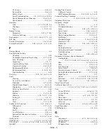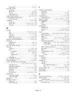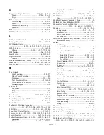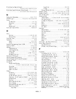
Index - 7
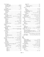
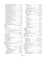
Multi-function Digital Outputs...............................................
...........................................2-9, 2-15, 2-19, 2-24, 5-53, A-15
Multi-step Speed Reference (Preset Speed) ...........................
............................................5-12, 5-39, 5-50, 5-51, A-4, A-8
N
Nameplate Information.......................................1-6, 1-7, 1-9
NEMA Type 1 ..........................1-2, to 1-5, 1-8, 1-16 to 1-19
Noise
Cooling Fan ........................................................ 7-2, 7-3
Electrical .......................................................... 1-8, 6-22
Filter ..........................................................................E-6
Mechanical .............................................5-42, 6-23, A-9
No-Load Current (NLA) ...................................... 5-48, A-11
O
OFF
Position....................................................1-10, 1-11, 4-8
Selector Key ....................................................... 3-2, 3-3
On-delay Timer ...................................................... 5-17, A-4
Operation ........................................................................ 4-10
Menu .............................................................. 3-11, 3-13
Status ......................................................1-10, 3-2, A-26
Operator Programming Errors (OPE)............................. 6-16
Operator MOP ...................................................... 5-75, A-24
Options ...................................................................1-7 to 1-9
And Enclosures ...............................................1-3 to 1-5
And Programming .....................................5-2, 5-6, 5-25
Card Faults ......................................................... 6-8, 6-9
LonWorks ........................................... v, 5-48, 7-8, A-11
Peripheral Devices ....................................................E-6
Optional LCD Keypad .............................. 1-9, 4-2, 5-2, A-1
Option Dependent Parameters.......................................... 5-6
Option Dependent PI Control Parameters ...................... 5-25
Orientation, Drive........................................................... 1-20
Oscillation
Mechanical Vibration ......................................................
...................... 1-19, 4-7, 5-41, 5-42, 6-23, 7-2, A-9, C-4
Prevention .............................................................. A-23
With PI control ........................................................ 6-23
With V/f control ...................................................... 6-23
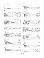
Output
Contactor ........................................... 1-13, 2-2, 4-5, F-4
Connections..................................... 1-12, 2-2, 2-6, 2-20
Current Monitor (U1-03).....................2-20, A-17, A-26
Frequency - (See Frequency, Output) ........... C-2 to C-3
Ground Fault ..........................................5-66, 6-9, A-22
Monitors ............................................. A-17, A-26, A-27
Power Monitor (U1-08).......................................... A-26
Power Ratings ........................................ 1-2, C-2 to C-3
Terminal Status Monitor (U1-11)........................... A-26
Transistors (IGBT)
Inspecting ........................................................... 7-2
Spare Parts .................................................. F-2, F-3
Testing ..............................................................6-27
Voltage Monitor (U1-06) ........................................ A-26
Outputs, Analog ................................ 2-13, 2-20, A-17, A-18
Outputs, Digital................. 2-9, 2-15, 2-19, 2-24, 5-53, A-15
Over Current (OC) ......................................... 4-6, 5-66, 6-10
Overheat (OH)
Alarms/Faults............5-69, 6-10, 6-14, A-19, A-22, B-3
And Auto Restart .....................................................5-66
Cooling Fin (Heatsink) .........6-10, 6-14, 7-2, A-22, C-4
Drive ..............................................................1-19, A-22
Motor .......................................... 6-10, 6-14, 6-22, A-19
Parameters ....................................................A-19, A-22
Pre-Alarm ......................................................6-14, A-22
Overload
Alarms/Faults.................................2-9, 3-10, 6-10, 6-14
And Auto Restart .....................................................5-66
Capacity .................................................................... C-4
Drive .............................................................. 5-47, 6-14
Indicator.....................................................................3-7
Motor .................................................. 6-10, A-15, A-19
Protection........................................................ A-19, C-4
Relay ................................. 1-12, 1-13, 2-2, 2-3, 4-5, 4-6
Overtorque - See Torque Detection ......................5-67, A-21
Overvoltage Protection ............................................ 6-11 C-4
And Auto Restart .....................................................5-66
DC Bus - See DC Bus Voltage ...............6-11, 6-15, C-4
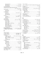
P
Parameters...........................................................A-1 to A-29
Accel/Decel (C1-01 - C1-11).................................... A-7
Analog Inputs (H3-02 - H3-13) .............................. A-16
Analog Outputs (H4-01 - H4-08) .................A-17, A-18
Auto-Tuning (T1-02 - T1-04) ................................. A-25
Capacity Related....................................................... B-1
Carrier Freq (C6-02 - C6-05).................................... A-8
Com OPT Setup (F6-01 - F6-05) ............................ A-11
COPY Function (o3-01 - o3-02)............................. A-25
DC Braking (b2-01 - b2-09) ..................................... A-4
Delay timers (b4-01 - b4-02) .................................... A-5
Digital Inputs (H1-01 - H1-05)..................A-12 to A-14
Digital Outputs (H2-01 - H2-02) ............................ A-15
Energy Saving (b8-01 - b8-06) ................................. A-7
Example of Changing ..............................................3-22
Factory Reset (Initialize) .......................................... A-2
Fault Restart (L5-01 - L5-03) ................................. A-21
Hdwe Protection (L8-01 - L8-19)........................... A-22
High Slip (n3-01 - n3-04) ....................................... A-23
Hunting Prevention (n1-01 - n1-02) ....................... A-23
Initialization (A1-00 - A1-05) ..................................A-2
Jump Frequencies (d3-01 - d3-04)............................A-9
Key Selections (o2-01 - o2-15) ....................A-24, A-25
Listing of E7L Defaults .................... Inside Front Cover
Modified .........................................................3-11, 3-20
Summary of Contents for E7LBA002
Page 1: ...E7L Drive Bypass Technical Manual Model E7L Document Number TM E7L 01 ...
Page 8: ...Introduction vi Notes ...
Page 12: ...Table of Contents x Notes ...
Page 54: ...Electrical Installation 2 22 Wiring Diagram ...
Page 55: ...Electrical Installation 2 23 ...
Page 87: ...Start Up and Operation 4 9 Notes ...
Page 202: ...Diagnostic Troubleshooting 6 30 Notes ...
Page 248: ...Capacity Related Parameters B 6 Notes ...
Page 279: ...Communications D 27 Note ...
Page 280: ...Communications D 28 ...
Page 292: ...Spare Parts F 6 ...
Page 304: ...Index 12 ...
Page 305: ......

