Control Panel 3 - 9
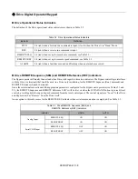
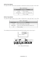
Selector Key Indicators
When off these selector key indicators simply mean that the function has not been selected. The table below describes the
operation when these functions are selected and the key indicator is lit.
Normal Control Panel Indicators
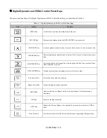
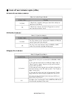
Table 3.17 Selector Key Indicators
Selector Key
LED Color
Function When Lit
Drive Select
Green
The Drive mode of operation is selected.
Bypass Select
Amber
The Bypass mode of operation is selected.
HAND
Amber
The Drive or Bypass is operated via the local control panel. A Run
command is automatic.
OFF
Amber
The Run command has been removed from the Drive or Bypass.
AUTO
Green
The Drive or Bypass is operated via a remote device (DDC or BAS).
Drive Test
Amber
The Drive is operated via the local control panel while the motor is
operating in Bypass mode.
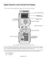
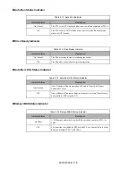
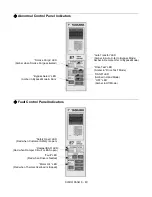
“Auto Run” LED
(Green with Auto Mode & Auto Start)
“Control Power” LED
(Green with Power Applied)
“Drive Select” LED
(Green in Drive Mode)
“Ready” LED
(Green indicates no problems)
“Run” LED
(Green indicates Run Command)
“Auto” LED
(Green in Auto Mode)
Summary of Contents for E7LBA002
Page 1: ...E7L Drive Bypass Technical Manual Model E7L Document Number TM E7L 01 ...
Page 8: ...Introduction vi Notes ...
Page 12: ...Table of Contents x Notes ...
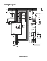
Page 54: ...Electrical Installation 2 22 Wiring Diagram ...
Page 55: ...Electrical Installation 2 23 ...
Page 87: ...Start Up and Operation 4 9 Notes ...
Page 202: ...Diagnostic Troubleshooting 6 30 Notes ...
Page 248: ...Capacity Related Parameters B 6 Notes ...
Page 279: ...Communications D 27 Note ...
Page 280: ...Communications D 28 ...
Page 292: ...Spare Parts F 6 ...
Page 304: ...Index 12 ...
Page 305: ......

