Programming 5 - 33
b5-17 PI Accel/Decel Time
Setting Range:
0.0 to 25.5 Seconds
Factory Default: 0.0 Seconds
This is a soft start function that is applied to the PI setpoint analog input. Instead of having nearly instantaneous changes in
signal levels, there is a programmed ramp applied to level changes. When changing setpoints the error can be limited by
gradually ramping the setpoint through the use of parameter b5-17.
b5-18 PI Setpoint Selection
In order to use parameter b5-19 as the PI Setpoint, set parameter b5-18= “1: Enabled”. If b5-18= “0: Disabled” the PI Setpoint
will either be:
•
Modbus Register 06H (If Register 0FH bit 1 is high)
•
The active speed command (i.e. Determined by the setting of b1-01). See Table 5.7 “Setpoint Options”
b5-19 PI Setpoint Value
Setting Range:
0.00 to 100.00%
Factory Default: 0.00%
Parameter b5-19 is for a PI Setpoint value. When b5-18= “1: Enabled”, the value of b5-19 will take precedent over any other PI
setpoint unless the Drive is set up for Differential Feedback, in which case, b5-18 and b5-19 have no affect on the PI
function.
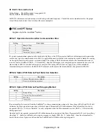
b5-20 PI Setpoint Display Scaling
The PI Setpoint Display Scaling value (b5-20) is a scaling factor that is applied to the monitor display for both the PI Setpoint
(U1-38) and the PI Feedback (U1-24).
Setting
Description
0
Disabled (
factory default
)
1
Enabled
Setting
Description
0
Hz (
factory default
)
1
%
3
RPM (Synchronous)
3
Engineering Units
Table 5.7 PI Setpoint Display Scaling Options
If b5-20 is:
U1-24 and U1-38
Display Increments.
0
0.01 Hz
1
0.00%
2 through 39
(enter the # of motor poles)
0 RPM
40 through 39999
Engineering Units
Summary of Contents for E7LBA002
Page 1: ...E7L Drive Bypass Technical Manual Model E7L Document Number TM E7L 01 ...
Page 8: ...Introduction vi Notes ...
Page 12: ...Table of Contents x Notes ...
Page 54: ...Electrical Installation 2 22 Wiring Diagram ...
Page 55: ...Electrical Installation 2 23 ...
Page 87: ...Start Up and Operation 4 9 Notes ...
Page 202: ...Diagnostic Troubleshooting 6 30 Notes ...
Page 248: ...Capacity Related Parameters B 6 Notes ...
Page 279: ...Communications D 27 Note ...
Page 280: ...Communications D 28 ...
Page 292: ...Spare Parts F 6 ...
Page 304: ...Index 12 ...
Page 305: ......


