Programming 5 - 15
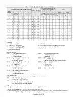
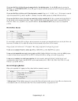
2:DCInj to Stop:
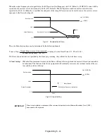
When the Run command is removed, the Drive will Baseblock (turn off its output) for the Minimum Base-
block Time (L2-03). Once the Minimum Baseblock Time has expired, the Drive will inject DC current into the motor wind-
ings to lock the motor shaft. The stopping time will be reduced as compared to Coast to Stop. The level of DC Injection
current is set by parameter b2-02 (50% Default). The DC Injection brake time is determined by the set value in b2-04 and
the output frequency at the time the Run command is removed.
Fig 5.4 DC Injection Braking to Stop
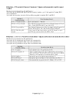
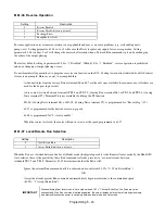
3:Coast w/Timer:
When the Run command is removed, the Drive will turn off its output and the motor will coast to a stop. If
a Run command is input before time T (Operation Wait Time) expires, the Drive will not run and the Run command will
need to be cycled before operation can occur
.
The time T (Operation Wait Time) is determined by the output frequency
when the Run command is removed and the active deceleration time (C1-02).
Fig 5.5 Coast to Stop with Timer
IMPORTANT
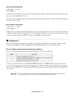
If an overcurrent (OC) fault occurs during DCInj to Stop, lengthen the Minimum Baseblock Time (L2-03)
until the fault no longer occurs.
04)
-
(E1
Frequency
Maximum
Frequency
Output
10
04)
-
(b2
Time
Brake
Injection
DC
×
×
=
ON
OFF
Run Command
Output Frequency
Drive Output Voltage Interrupted
DC Injection Brake
DC Injection Brake Time
Minimum Baseblock
Time (L2-03)
100 %
0 %
D
C
In
je
ct
io
n
Br
a
k
e
T
im
e
b2-04 x 10
b2-04
10%
100% (Maximum
Output Frequency)
b2-04
(CLOSED)
(OPEN)
Run Command
Output Frequency
Drive Output
Voltage
Interrupted
OFF
ON
Timer Value T
(C1-02)
100 %
0 %
Op
er
ati
o
n
Wai
t T
im
e
(T
)
Deceleration
Time (C1-02)
Minimum
Baseblock
Time (L2-03)
Minimum
Output
Frequency
100% (Maximum
Output
Frequency)
Output Frequency at Stop Command Input
Ignored
Run Command
Timer Value T
(OPEN)
(CLOSED)
Summary of Contents for E7LBA002
Page 1: ...E7L Drive Bypass Technical Manual Model E7L Document Number TM E7L 01 ...
Page 8: ...Introduction vi Notes ...
Page 12: ...Table of Contents x Notes ...
Page 54: ...Electrical Installation 2 22 Wiring Diagram ...
Page 55: ...Electrical Installation 2 23 ...
Page 87: ...Start Up and Operation 4 9 Notes ...
Page 202: ...Diagnostic Troubleshooting 6 30 Notes ...
Page 248: ...Capacity Related Parameters B 6 Notes ...
Page 279: ...Communications D 27 Note ...
Page 280: ...Communications D 28 ...
Page 292: ...Spare Parts F 6 ...
Page 304: ...Index 12 ...
Page 305: ......

