Programming 5 - 73
o1-03 Digital Operator Display Scaling
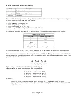
Parameter o1-03 allows the programmer to change the units in which the speed monitors and some speed parameters are displayed.
The o1-03 parameter will change the units of the following:
•
U1-01 (Frequency Reference Monitor)
•
U1-02 (Output Frequency Monitor)
•
U1-20 (Output Frequency after Soft Start)
•
d1-01 through d1-17 (Preset Frequency References and Jog Reference)
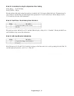
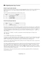
The table below details how the setting of o1-03 will affect the way the listed monitors and parameters will be displayed.
The factory default setting (o1-03= “0”) sets the Drive up to display the affected monitors and parameters in terms of hertz (Hz).
If the speeds seem more natural in terms of percentage of maximum, set o1-03= “1”. If the speeds are easier to work with when dis-
playing the equivalent synchronous motor RPM, set o1-03= [the number of motor poles]. If another engineered unit, such as fpm or
gpm, is desired, set o1-03= xxxx where:
X X X X X
Digit 5 Digit 4 Digit 3 Digit 2 Digit 1
Digits 1 through 4 set the desired number to be displayed at 100% speed.
Digit 5 determines the number of decimal places in the displayed number.
If Digit 5 = 0 number format is XXXX
If Digit 5 = 1 number format is XXX.X
If Digit 5 = 2 number format is XX.XX
If Digit 5 = 3 number format is X.XXX
For example:
If o1-03= 10425, then at full speed the digital operator will display “42.5”. Configuring parameter o1-03 for
displaying in terms of an engineering unit is only appropriate if the actual display units have a linear relationship with the
actual output speed.
Setting
Description
0
Hz (
factory default
)
1
%
2 - 39
RPM (Enter the # of Motor Poles)
40 - 39999
User Display
Table 5.18 Display Scaling
If o1-03 is:
The frequency format is
0
0.01 Hz
1
0.00%
2 through 39
(enter the # of motor poles)
0 RPM
40 through 39999
Engineering Units
Summary of Contents for E7LBA002
Page 1: ...E7L Drive Bypass Technical Manual Model E7L Document Number TM E7L 01 ...
Page 8: ...Introduction vi Notes ...
Page 12: ...Table of Contents x Notes ...
Page 54: ...Electrical Installation 2 22 Wiring Diagram ...
Page 55: ...Electrical Installation 2 23 ...
Page 87: ...Start Up and Operation 4 9 Notes ...
Page 202: ...Diagnostic Troubleshooting 6 30 Notes ...
Page 248: ...Capacity Related Parameters B 6 Notes ...
Page 279: ...Communications D 27 Note ...
Page 280: ...Communications D 28 ...
Page 292: ...Spare Parts F 6 ...
Page 304: ...Index 12 ...
Page 305: ......


