Programming 5 - 27
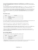
Discussion of Table 5.4 Options Dependent, PI Control Bypass Parameter Settings:
Typical Drive Parameter Settings for PI Control with Various Combinations of Bypass and Control Options
Notes:
For project specific PI control tuning see the PI Control (b5-XX) parameters in this chapter. Tables 5.3 and 5.4
provide the basic configuration for PI Control from a Drive in an E7L Bypass unit. The b5-XX parameters are
defaulted to a good starting point for most HVAC applications. Final adjustment to some of the b5-XX parameters for
the project at hand may be required.
Hand mode run/stop for Drive and Bypass is always via the front control panel HAND/OFF/AUTO selector.
Options - None;
Bypass with PI Control and no options:
Hand mode speed command from Keypad/Operator.
Auto mode PI Setpoint from Keypad/Operator.
Auto mode PI Feedback input signal, 4-20 mA applied to Terminal TB3-3 (Drive terminal A2).
Auto mode run/stop contact closure for Drive and Bypass applied to terminals TB1-2 and TB1-9.
Options - None;
Bypass with PI Control and no options:
Hand mode speed command from Keypad/Operator.
Auto mode PI Setpoint from Keypad/Operator.
Auto mode PI Feedback input signal, 0-10 VDC applied to Terminal TB3-3 (Drive terminal A2).
Auto mode run/stop contact closure for Drive and Bypass applied to terminals TB1-2 and TB1-9.
Significant
Parameter Setting
Drive Operational Result
b1-01 = 0: Operator
Speed command (Hand) and PI setpoint (Auto) source = Keypad/Operator (U1-01)
b5-01 = 1: Enable
Enable PI mode of operation
H1-03 = 19: PI Disable
A Drive terminal S5 input contact closure disables PI mode. This input contact is
closed when H/O/A = Hand.
H3-08 = 2: 4-20 mA (default)
Drive Terminal A2 is programmed for 4-20 mA (Note – Control PCB DIP switch
S1-2 must also be ON)
H3-09 = B: PI Feedback
Drive Terminal A2 function is set to provide PI feedback for closed loop control
Significant
Parameter Setting
Drive Operational Result
b1-01 = 0: Operator
Speed command (Hand) and PI setpoint (Auto) source = Keypad/Operator (U1-01)
b5-01 = 1: Enable
Enable PI mode of operation
H1-03 = 19: PI Disable
A Drive terminal S5 input contact closure disables PI mode. This input contact is
closed when H/O/A = Hand.
H3-08 = 0: 0-10 VDC
Drive Terminal A2 is programmed for 0-10 VDC (Note – Control PCB DIP switch
S1-2 must also be OFF)
H3-09 = B: PI Feedback
Drive Terminal A2 function is set to provide PI feedback for closed loop control
Summary of Contents for E7LBA002
Page 1: ...E7L Drive Bypass Technical Manual Model E7L Document Number TM E7L 01 ...
Page 8: ...Introduction vi Notes ...
Page 12: ...Table of Contents x Notes ...
Page 54: ...Electrical Installation 2 22 Wiring Diagram ...
Page 55: ...Electrical Installation 2 23 ...
Page 87: ...Start Up and Operation 4 9 Notes ...
Page 202: ...Diagnostic Troubleshooting 6 30 Notes ...
Page 248: ...Capacity Related Parameters B 6 Notes ...
Page 279: ...Communications D 27 Note ...
Page 280: ...Communications D 28 ...
Page 292: ...Spare Parts F 6 ...
Page 304: ...Index 12 ...
Page 305: ......


