Programming 5 - 12
A1-04 Password Entry
Setting Range:
0 to 9999
Factory Default: 0
If parameters A1-01 through A1-03 and all of the A2 parameters are locked (unchangeable) they can be unlocked by entering
the correct password number into A1-04.
Once the correct password number is entered and the specified parameters are unlocked, a 2-Wire or 3-Wire initialization will
reset the password to 0000.
A1-05 Select Password
Setting Range:
0 to 9999
Factory Default: 0
When the value set into A1-04 does NOT match the value set into A1-05, parameters A1-01 thru A1-03 and A2-32 cannot be
changed. All other parameters determined by A1-01 can be changed. Parameter A1-05 can be accessed by displaying parame-
ter A1-04, then press and hold the RESET key along with the MENU key simultaneously.
b1 Sequence
The Sequence Group contains parameters associated with starting and stopping the Drive. Parameters involving the Run
Command, Speed Reference location, Stopping Method and Hand/Auto changeover are located in this group.
b1-01 Reference (Speed Command) Source Selection
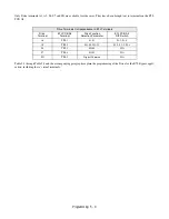
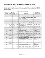
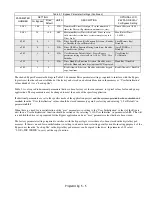
This is one of the special parameter settings required by the Bypass logic circuit. See Table 5.1.
In order to run the Drive and motor with the BYPASS/DRIVE select keys in the DRIVE Select position: the Drive must
receive a Run command and a speed command. Parameter b1-01 specifies from where the speed command is received when
the Drive is in the
AUTO
mode. Switching into the
AUTO
mode can be done by pressing the AUTO key of the Hand/Off/
Auto selector.
Setting
Description
0
Operator - Digital Preset Speed d1-01
1
Terminals - Analog Input Terminal A1 (or Terminal A2, see Parameter H3-13)
2
Serial Com - RS-485 Terminals R+, R-, S+ and S-
3
Option PCB - Option Board connected at 2CN
IMPORTANT
If a Run command is input to the Drive but no corresponding speed command is input, the Run indicator on
the digital operator will turn on and the STOP indicator on the digital operator will blink.
Summary of Contents for E7LBA002
Page 1: ...E7L Drive Bypass Technical Manual Model E7L Document Number TM E7L 01 ...
Page 8: ...Introduction vi Notes ...
Page 12: ...Table of Contents x Notes ...
Page 54: ...Electrical Installation 2 22 Wiring Diagram ...
Page 55: ...Electrical Installation 2 23 ...
Page 87: ...Start Up and Operation 4 9 Notes ...
Page 202: ...Diagnostic Troubleshooting 6 30 Notes ...
Page 248: ...Capacity Related Parameters B 6 Notes ...
Page 279: ...Communications D 27 Note ...
Page 280: ...Communications D 28 ...
Page 292: ...Spare Parts F 6 ...
Page 304: ...Index 12 ...
Page 305: ......


