Peripheral Devices E - 2
Branch Circuit Short Circuit Protection
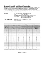
The following peripheral devices may be required between the AC main circuit power supply and the Drive input
terminals L1(R), L2(S), and L3(T). Refer to applicable codes to determine the devices necessary for a given
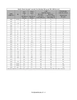
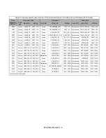
installation. Use Table E.1 or E.2 when selecting fuses and circuit breakers per the NEC. When selecting
semiconductor fuses to provide Drive input I
2
t protection and comply with UL, CSA, NEC, and CEC branch circuit
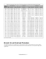
short circuit protection requirements, select one of the fuses in Table E.3 or E.4.
Fuse Type:
UL designated Time-Delay or Non-Time-Delay Fuse
Class:
CC, J, T, RK1 or RK5
Designators (typical):KTK, FNQ, FRS, LPJ, LPS, JKS, JJN, or JJS
Voltage Rating:
250V for Drives with 208-240V input
600V for Drives with 480V input
Circuit Breaker Type:
Inverse Time (MCCB) or Instantaneous Trip (MCP)
Voltage Rating: 600V
Table E.1 Recommended Fuse and Circuit Breaker Ratings per NEC (208-240Vac Input)
Model
CIMR-E7U
Hp
Input
Amps
*1
(Continuous
Rating)
Output
Amps
*1
(Continuous
Rating)
Fuse
Selection Criteria
Circuit Breaker
Selection Criteria
Maximum
Time-Delay
Fuse Rating (A)
Maximum
Non-Time-Delay
Fuse Rating (A)
Maximum CB
Rating (A)
20P4
0.5/0.75
4.3
3.6
6
12
15
20P7
1
5.5
4.6
8
12
15
21P5
1.5/2
9.4
7.8
15
15
15
22P2
3
13
10.8
20
20
20
23P7
5
20
16.8
30
30
35
25P5
7.5
24
23
40
50
45
27P5
10
37
31
60
80
80
2011
15
53
46.2
80
80
100
2015
20
70
59.4
110
125
125
2018
25
89
74.8
125
150
150
2022
30
98
88
150
150
175
2030
40
120
115
200
200
225
2037
50
180
162
250
250
300
2045
60
212
192
300
300
350
2055
75
237
215
350
350
450
2075
75/100
350
312
450
450
600
2090
125
396
360
600
600
700
2110
150
457
415
700
700
900
*1 Input and Output Amps are based on the Normal Duty (ND) current rating. Consult the Specification section for details on the Heavy Duty (HD) and Normal Duty (ND) ratings.
Summary of Contents for E7LBA002
Page 1: ...E7L Drive Bypass Technical Manual Model E7L Document Number TM E7L 01 ...
Page 8: ...Introduction vi Notes ...
Page 12: ...Table of Contents x Notes ...
Page 54: ...Electrical Installation 2 22 Wiring Diagram ...
Page 55: ...Electrical Installation 2 23 ...
Page 87: ...Start Up and Operation 4 9 Notes ...
Page 202: ...Diagnostic Troubleshooting 6 30 Notes ...
Page 248: ...Capacity Related Parameters B 6 Notes ...
Page 279: ...Communications D 27 Note ...
Page 280: ...Communications D 28 ...
Page 292: ...Spare Parts F 6 ...
Page 304: ...Index 12 ...
Page 305: ......


