Programming 5 - 26
Optional LCD Digital Operator and Control Panel Display for PI Control
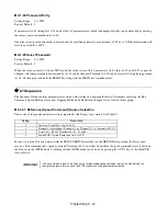
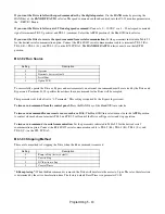
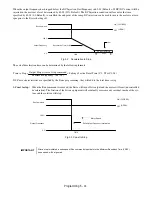
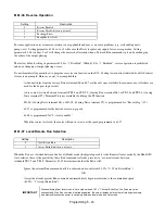
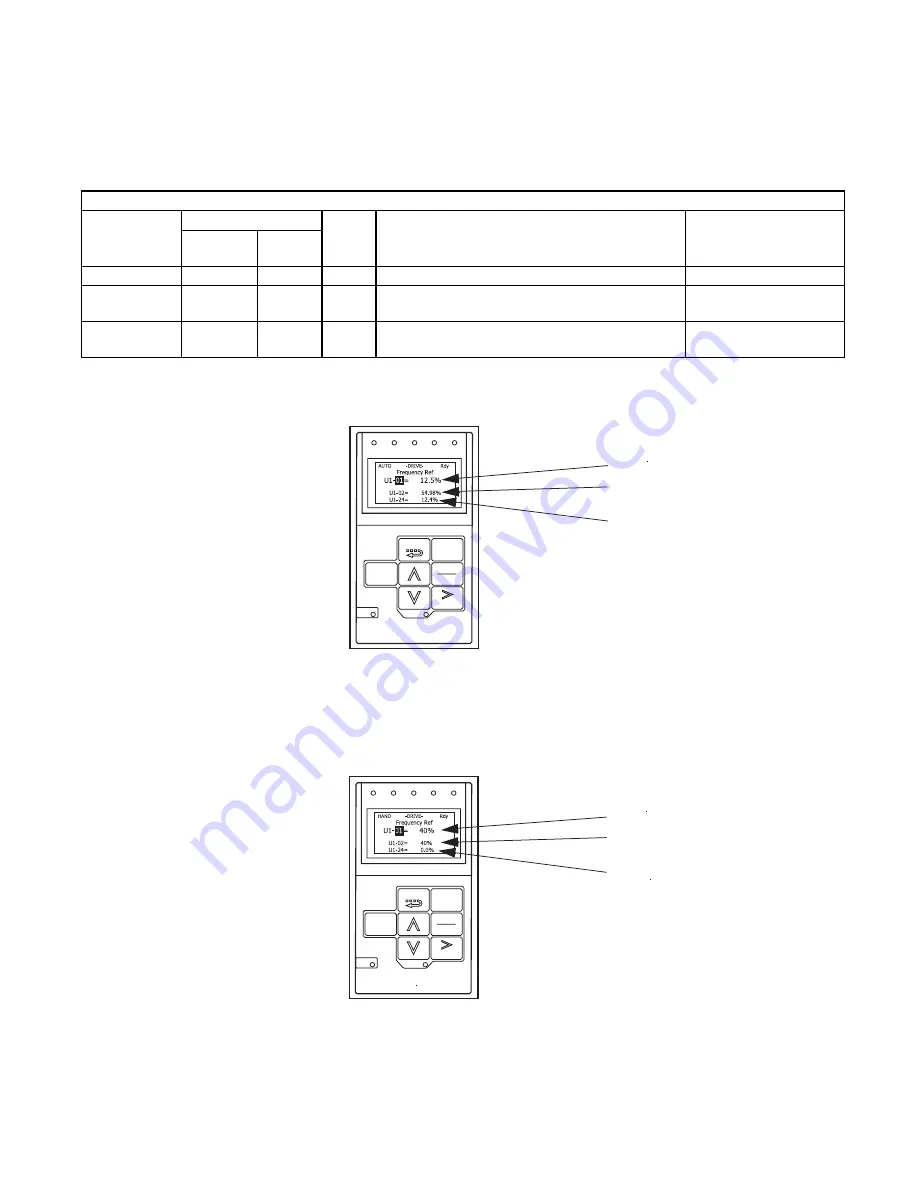
In Table 5.5, the o1-0X parameter listed setup the Drive display to indicate 3 variables for PI control as in Figure 5.14 when
the HAND/OFF/AUTO selector is in
AUTO
.
Table 5.5 parameter for optional LCD display setup for PI control.
Fig 5.14 Drive Display for PI Control, AUTO Mode
When the HAND/OFF/AUTO selector is transfered to the
HAND
position, the display will automatically change to indicate
the speed command, as in Figure 5.15.
Fig 5.15 Drive Display for PI Control, HAND Mode
Table 5.5 Parameters for Optional LCD Display Setup for PI Control
PARAMETER
NUMBER
SETTING
UNITS
DESCRIPTION
KEYPAD DISPLAY
For Bypass Setting
For Bypass
Drive
Default
o1-03
1
0
%
Digital Operator Display Selection – Set for percent
Display Scaling / (0-39999)
o1-06
1
0
N/A
User Monitor Selection Mode – Enables a custom
display for PI Control monitoring
Monitor Mode Sel / 1: 3
Non Selectable
o1-08
24
3
N/A
Third Line User Monitor Selection – Display PI
Feedback
3rd Monitor Sel / 24: PI
Feedback
PI SETPOINT
FWD
REV
SEQ
REF
ALARM
AUTO
- - - - - - - - - - - - - - - - - - - - - - - - - - - - -
OUTPUT
PI FEEDBACK
RUN
Monitor
DATA
ESC
MENU
ENTER
RESET
STOP
FWD
REV
SEQ
REF
ALARM
AUTO
RUN
Monitor
DATA
ESC
MENU
ENTER
RESET
STOP
SPEED COMMAND
- - - - - - - - - - - - - - - - - - - - - - - - - - - - -
OUTPUT
FEEDBACK
Summary of Contents for E7LBA002
Page 1: ...E7L Drive Bypass Technical Manual Model E7L Document Number TM E7L 01 ...
Page 8: ...Introduction vi Notes ...
Page 12: ...Table of Contents x Notes ...
Page 54: ...Electrical Installation 2 22 Wiring Diagram ...
Page 55: ...Electrical Installation 2 23 ...
Page 87: ...Start Up and Operation 4 9 Notes ...
Page 202: ...Diagnostic Troubleshooting 6 30 Notes ...
Page 248: ...Capacity Related Parameters B 6 Notes ...
Page 279: ...Communications D 27 Note ...
Page 280: ...Communications D 28 ...
Page 292: ...Spare Parts F 6 ...
Page 304: ...Index 12 ...
Page 305: ......

