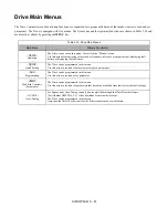

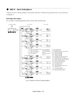

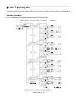
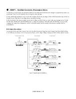


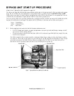


Start Up and Operation 4 - 3
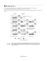
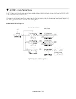
The BAS Interlock Circuit at Power Up
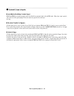
When a Run command is received in HAND or AUTO mode, the E7L will display a red “Damper/Bas” LED in the “System
Status” area of the front control panel. This condition will prevent Drive or Bypass operation.
One of the following three items needs to be done prior to start-up:
1)
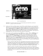
Install a “BAS Interlock Circuit” between TB1-3 and TB1-9 on PCB A2.
2)
Install a jumper between TB1-3 and TB1-9 on PCB A2. This method should be used if a “BAS Interlock Circuit” will be
added later in the installation.
3)
De-activate these terminals by moving DIP switch S2-8 to the ON position (toward the enclosure door). This solution is
only suggested if a “Safety Circuit” will never be applied to the drive system.
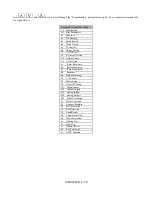
Summary of Contents for E7LBA002
Page 1: ...E7L Drive Bypass Technical Manual Model E7L Document Number TM E7L 01 ...
Page 8: ...Introduction vi Notes ...
Page 12: ...Table of Contents x Notes ...
Page 54: ...Electrical Installation 2 22 Wiring Diagram ...
Page 55: ...Electrical Installation 2 23 ...
Page 87: ...Start Up and Operation 4 9 Notes ...
Page 202: ...Diagnostic Troubleshooting 6 30 Notes ...
Page 248: ...Capacity Related Parameters B 6 Notes ...
Page 279: ...Communications D 27 Note ...
Page 280: ...Communications D 28 ...
Page 292: ...Spare Parts F 6 ...
Page 304: ...Index 12 ...
Page 305: ......