Programming 5 - 56
H3-08 Drive Terminal A2 Signal Level
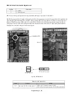
H3-08 is one of the special parameter settings required by the Bypass logic circuit. See Table 5.2.
The H3-08 parameter (Drive Terminal A2 Signal Level) allows the programmer to specify the signal that will be applied to the
A2 analog input (E7L Terminal TB3-3 or TB5-9). The A2 analog input can accept either a 0–10 Vdc or 4-20 mA signal as a
reference. The E7L also has a DIP switch (S1) on the PCB A2 that must be set for the proper reference signal into the A2
analog input. The S1-2 DIP switch setting determines the internal resistance of the Drive A2 input while parameter H3-08
determines how the Drive interprets the measured signal.
Fig 5.28 DIP Switch S1
Setting
Description
0
0 - 10VDC
2
4 - 20mA (Default)
Table 5.15 DIP Switch S1-2
Name
Function
Setting
S1-2
Input signal for Drive analog input A2
OFF: 0 to 10 V (internal resistance: 20 k
Ω
)
ON: 4 to 20 mA (internal resistance: 250
Ω
) (Factory default)
DIP Switch S1 example
2
3
4
1
O
Location of S1
S1-2
Summary of Contents for E7LBA002
Page 1: ...E7L Drive Bypass Technical Manual Model E7L Document Number TM E7L 01 ...
Page 8: ...Introduction vi Notes ...
Page 12: ...Table of Contents x Notes ...
Page 54: ...Electrical Installation 2 22 Wiring Diagram ...
Page 55: ...Electrical Installation 2 23 ...
Page 87: ...Start Up and Operation 4 9 Notes ...
Page 202: ...Diagnostic Troubleshooting 6 30 Notes ...
Page 248: ...Capacity Related Parameters B 6 Notes ...
Page 279: ...Communications D 27 Note ...
Page 280: ...Communications D 28 ...
Page 292: ...Spare Parts F 6 ...
Page 304: ...Index 12 ...
Page 305: ......


