


5.1 Speed Control Operation
5-3
Spindle Axis
Operation
Note 1. The VELCTRL (3C hex) command does not accept speed feedforward (VFF) references. Create a speed refer-
ence that includes the speed feedforward in the host controller.
2. You can select the gain (SVCMD_IO.G-SEL) with the VELCTRL (3C hex) command as well.
However, the SERVOPACK’s position loop gain (kp) does not affect motor behavior.
Prepare the position loop gain (kp) at the host controller and select the position loop gain to match the gain selec-
tion (SVCMD_IO.G-SEL).
Speed references for the VELCTRL (3C hex) command are in reference units/s, but for spindle axes the refer-
ence unit is in pulses, so the speed reference is given in pulses/s.
If the pulse encoder conforms to standard specifications, the speed reference for a spindle axis is 4,096 pulses/
rev.
Some spindle axes are equipped with gears and gear-switching functions, depending on the machine. In this
case, the gear ratio must be maintained from the host controller and the VREF speed reference must be speci-
fied as the motor speed based on that gear ratio.
Note: The number of pulses is the number of feedback pulses per single rotation of the spindle motor.
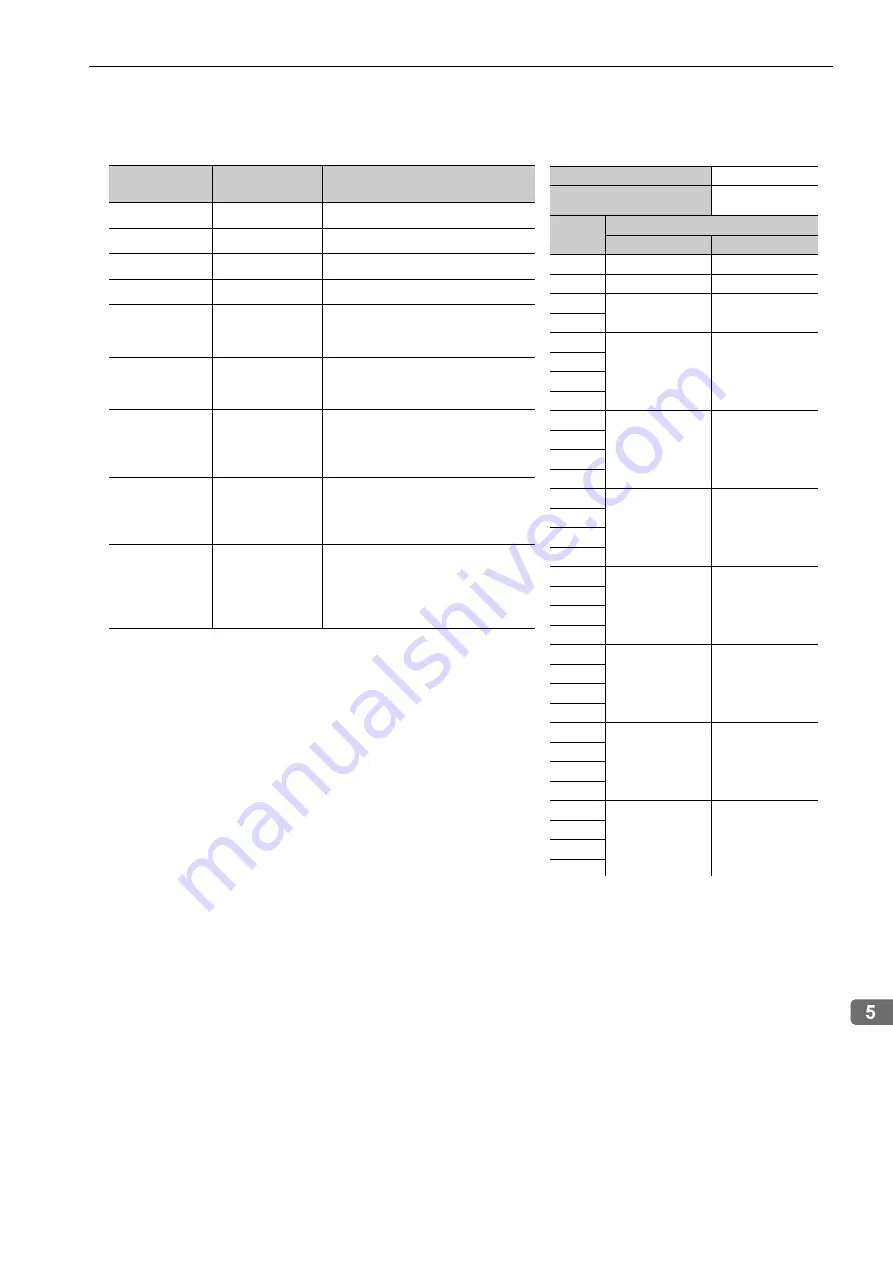
Command
Field
Meaning
Description
CMD
-
Ox3C
CMD_CTRL
-
-
SVCMD_CTRL
-
-
SVCMD_IO
-
-
TFF
Torque Feedfor-
ward
The torque unit is set in common
parameters 47 and 48. Normally, the
percent of the rated torque is selected.
VREF
Speed Reference
The speed unit is set in common
parameters 41 and 42. Normally, ref-
erence units/s is selected.
ACCR
Acceleration Rate
When the host controller is used to
perform position control, set the max-
imum acceleration rate (FFFF FFFF
hex).
DECR
Deceleration Rate
When the host controller is used to
perform position control, set the max-
imum deceleration rate (FFFF FFFF
hex).
TLIM
Torque Limit
The torque unit is set in common
parameters 47 and 48.
Note: The torque limit setting is
ignored for a spindle axis (i.e.,
when Pn01E.0 is 3).
Usable Phase
2 or 3
Processing Time
Within the communi-
cations cycle
Byte
VELCTRL
Command
Response
0
3C hex
3C hex
1
WDT
RWDT
2
CMD_CTRL
CMD_STAT
3
4
SVCMD_CTRL
SVCMD_STAT
5
6
7
8
SVCMD_IO
SVCMD_IO
9
10
11
12
TFF
CPRM_SEL_
MON1
13
14
15
16
VREF
CPRM_SEL_
MON2
17
18
19
20
ACCR
MONITOR1
21
22
23
24
DECR
MONITOR2
25
26
27
28
TLIM
MONITOR3
29
30
31