


5.6 Winding Selection
5-27
Spindle Axis
Operation
5.6.2
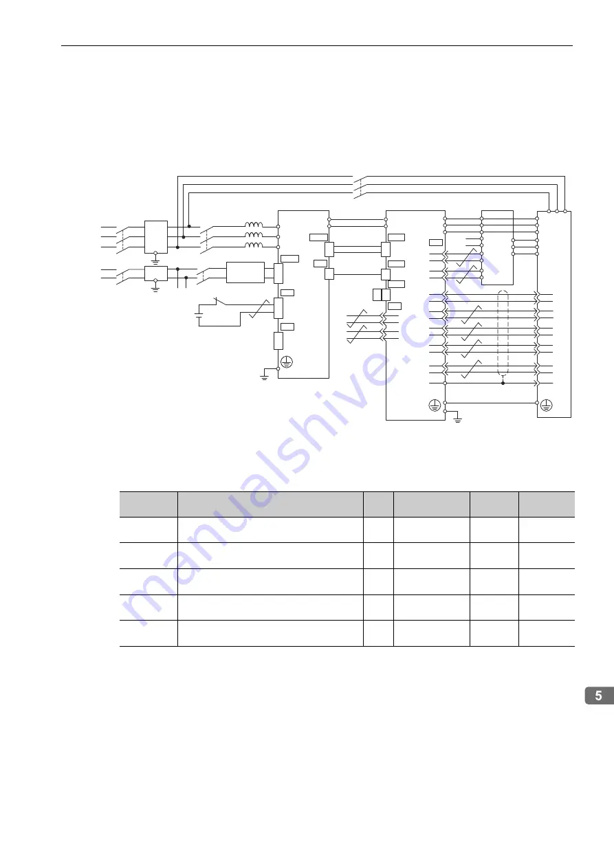
Winding Selection Motor Standard Connections Diagram
As shown in the following diagram, this system requires winding selection signals in addition to speed refer-
ence signals such as the FWD and REV signals.
A special magnetic contactor that can be driven directly from the SERVOPACK with transfer contacts is also
used to switch the winding.
∗
Connected to the CN3 connector shell.
5.6.3
Related Parameters
The parameters related to winding selection are listed below.
The flux level and base speed ratio control parameters are used to expand the constant-torque range for tap-
ping and other operations.
R
S
T
1QF
1FIL
1KM
2KM
U
V
W
X
Y
Z
CACP-JU
3A
L1
L2
L3
CN7A
24 V
0 V
CN1
/ESP+
+
-
/ESP-
CN7B
CN7A
CACR-JU
ADA
P
N
P
N
11
12
THM+
THM-
PC
/PC
PB
/PB
PA
/PA
2FIL
r
t
2QF
r1 t1
200/400 VAC
200 VAC
CA1
CA2
C24V
CC
CN3
13
14
15
16
2
4
6
U
V
W
+5V
GND
U
V
W
X
Y
Z
9
11
7
1
2
3
4
5
6
7
8
11
12
10
17
18
r1
t1
Z1Z2 Z3
3KM
CN5
CN5B
CN5A
CN3
CN6
MON1
GND
MON2
GND
1
3
2
4
8
9
14
15
18
19
16
17
12
13
10
11
1,2,3
4,5,6
∗
Motor
Ground resistance:
100
Ω
or less
Digital
Operator
24-VDC external
power supply
Terminating
resistance
Local bus
Control
power supply
(24 VDC)
Magnetic contactor
for winding selection
Parameter
No.
Name
Unit
Setting Range
Factory
Setting
When
Enabled
Pn01E
Application Function Select Switch 1E
-
0x0000 to 0x0025
0x0000
After
restarting
Pn433
Servo Mode Flux Level
(for High-speed Winding)
%
30 to 100
100
Immediately
Pn434
Servo Mode Base Speed Ratio
(for High-speed Winding)
%
100 to 500
100
Immediately
Pn435
Servo Mode Flux Level
(for Low-speed Winding)
%
30 to 100
100
Immediately
Pn436
Servo Mode Base Speed Ratio
(for Low-speed Winding)
%
100 to 500
100
Immediately