


9 Monitoring
9-4
89
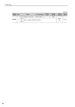
PnB12
4
0006 hex
SV_STAT
Monitor Description
1st byte: Current communications phase
00 hex: Phase 0
01 hex: Phase 1
02 hex: Phase 2
03 hex: Phase 3
2nd byte: Current control mode
00 hex: Position Control Mode
01 hex: Speed Control Mode
02 hex: Torque Control Mode
3rd byte: Reserved.
4th byte: Extended signal monitor
0000
Immediately
Setup
0007 hex Reserved parameter (Do not set.)
0008 hex
INIT_PGPOS (Low)
This is the lower 32 bits of the 64-bit data representing
the initial encoder position converted to reference
units.
0009 hex
INIT_PGPOS (High)
This is the upper 32 bits of the 64-bit data representing
the initial encoder position converted to reference
units.
8A
PnB14
4
Monitor Selection for SEL_MON2
(CMN2)
0 to 9
−
0000
Immediately
Setup
0000 hex
to
0009 hex
Same as Monitor Selection for SEL_MON1.
(cont’d)
Param-
eter No.
Size
Name
Setting
Range
Setting Unit
(Resolution)
Factory
Setting
When
Enabled
Classi-
fication
Bit
Name
Description
Set Value
Bit 0
LT_RDY1
Latch detec-
tion process-
ing status for
SVCMD_CT
RL.LT_REQ1
0: Latch detec-
tion not pro-
cessed.
1: Processing
latch detection.
Bit 1
LT_RDY2
Latch detec-
tion process-
ing status for
SVCMD_CT
RL.LT_REQ2
0: Latch detec-
tion not pro-
cessed.
1: Processing
latch detection.
Bits 2
and 3
LT_SEL1R Latch signal
0: Phase C
1: External
input 1
2: External
input 2
3: External
input 3
Bits 4
and 5
LT_SEL2R Latch signal
0: Phase C
1: External
input 1
2: External
input 2
3: External
input 3
Bit 6
Reserved (0).