


7 Alarm and Warning Processing
7.6.3 Using the SERVOPACK to Perform Emergency Stop Processing and the Host Controller to Turn OFF the Main Circuit
7-18
7.6.3
Using the SERVOPACK to Perform Emergency Stop Processing and the
Host Controller to Turn OFF the Main Circuit
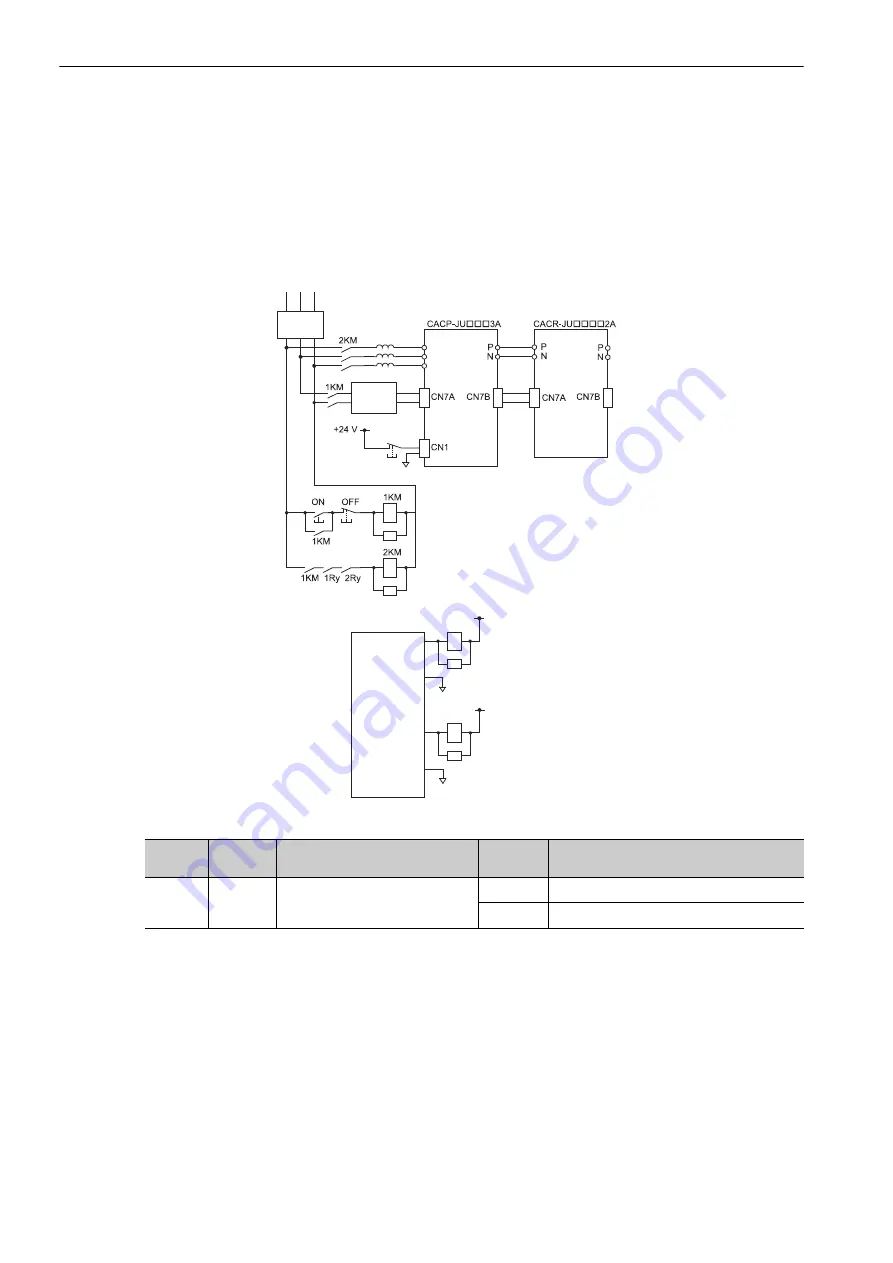
Perform the following wiring to use the SERVOPACK to perform emergency stop processing.
Connect the emergency stop switch to the power regeneration converter’s CN1 connector (/ESP+ and
/ESP-).
Axis stop processing is performed by the SERVOPACK, and the host controller controls the main circuit mag-
netic contactor (2KM).
(1) Signal Wiring and Related Parameters
To use the SERVOPACK to perform emergency stop processing, set the required parameters as described in
7.6.1 (1) Emergency Stop Selection
,
7.6.1 (3) Emergency Stop Torque
, and
7.6.1 (6) Emergency Stop Signal
Monitor
.
(2) Emergency Stop Processing
When the emergency stop signal turns OFF (emergency stop state), the SERVOPACK performs the following
processing.
• The axes that are in motion (both spindle and feed axes) decelerate to a stop at the torque that is set in
parameter Pn406 (Emergency Stop Torque).
If the servomotor for each axis is not stopped within 10 seconds after the emergency stop signal turns OFF
(emergency stop state), an Emergency Stop Operation Failure Alarm (A.6B0) will occur.
• The axes are base-blocked after they stop.
• Confirm that SVCMD_IO.ESTP2 changes from 0 to 1 for each SERVOPACK.
• Use the SMON (30 hex) command for all axes.
R S T
1Ry
24 V
ALM+
0V
ALM-
2Ry
24 V
SVM+
0 V
SVM-
0 V
Controller
Emergency
stop
Control
power supply
(24 VDC)
SERVOPACK
Converter
AC reactors
Filter
Type
Signal
Name
Power Regeneration Converter
Connector Pin Numbers
Setting
Meaning
Input
/ESP+
/ESP-
CN1-11, CN1-12
ON
Emergency stop released (normal operation).
OFF
Emergency stop