


4 Feed Axis Operation
4.1.1 How to Use the INTERPOLATE (34 Hex) Command
4-4
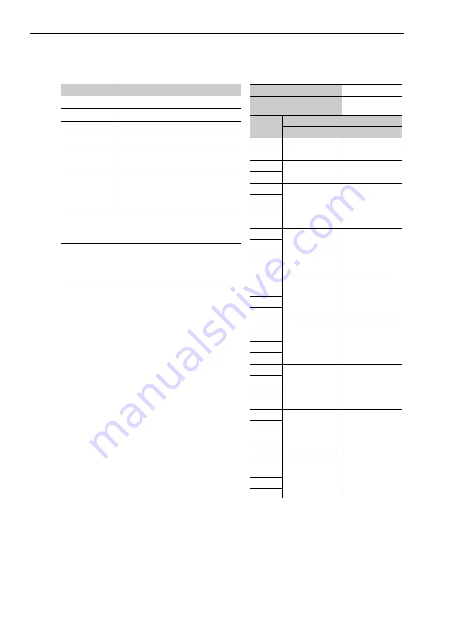
The following tables give the details of the INTERPOLATE (34 hex) command.
Note 1. The target position is the reference that is used to drive the actual servomotor.
The combination of the acceleration/deceleration profile, backlash offset, and pitch error correction from the host
controller is sent to the SERVOPACK as the target position (TPOS).
2. The speed feedforward (VFF) is set by changing the unit from
Δ
reference target value/communications cycle to
reference units/s.
3. Set the following control functions as needed.
• SVCMD_CTRL.ACCFIL (Acceleration/Deceleration Filter)
• SVCMD_CTRL_LTREQ (Latch Request)
• SVCMD_IO.GSEL (Gain Select)
Field
Description
CMD
Ox34
CMD_CTRL
–
SVCMD_CTRL
–
SVCMD_IO
–
TPOS
Target Position
The reference unit is set in common parame-
ters 43 and 44.
VFF
Speed Feedforward
The speed unit is set in common parameters
41 and 42. Normally, reference units/s is
selected.
TFF
Torque Feedforward
The torque unit is set in common parameters
47 and 48. Normally, the percent of the rated
torque is selected.
TLIM
Torque Limit
The torque unit is set in common parameters
47 and 48.
Normally, FFFF FFFF hex (i.e., no torque
limit) is set.
Usable Phase
3
Processing Time
Within the commu-
nications cycle
Byte
INTERPOLATE
Command
Response
0
34 hex
34 hex
1
WDT
RWDT
2
CMD_CTRL
CMD_STAT
3
4
SVCMD_CTRL
SVCMD_STAT
5
6
7
8
SVCMD_IO
SVCMD_IO
9
10
11
12
TPOS
CPRM_SEL_
MON1
13
14
15
16
VFF
CPRM_SEL_
MON2
17
18
19
20
TFF
MONITOR1
21
22
23
24
Reserved
MONITOR2
25
26
27
28
TLIM
MONITOR3
29
30
31